
Location Details
Constructivity Model Editor
| Read | Try | Buy |
|
|
|
Licenses may be purchased for $799 USD. VISA and MasterCard accepted 9AM-5PM Central US Time at +1.888.505.0996, or email info@constructivity.com for other arrangements. |
Construction Productivity
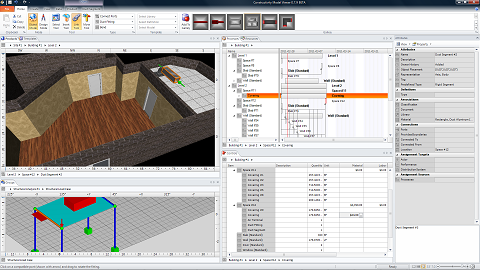
Constructivity software is designed to make construction more productive by bringing building information together in one place. The single unified interface provides access to building components, product geometry, analysis models, automation systems, cost estimates, construction schedules, contracts, and much more.
As a unified environment, all information connects intelligently – if you change a wall, you can immediately see the impact to structural analysis, energy usage, cost, and schedule.
Collaboration
Constructivity helps keep your project teams in sync, by organizing information in a central repository where you can track revisions and review changes made by others.
Constructivity allows you to see the history of every building component, cost entry, and construction task.
All in the Details
Don’t let the simplified interface fool you – Constructivity runs deep with features and capabilities.
Architectural modeling supports hundreds of parametric elements for conceptual design, and access to thousands of vendor product models for detailed design.
Engineering modeling supports structural analysis, finite element analysis, custom shapes, custom materials, and custom loads.
Construction modeling supports nested tasks, recurring tasks, 4D walkthroughs, custom calendars, and custom resource leveling.
Operation modeling supports device connectivity, deployment, monitoring, and control for building automation and communications.
Future Proof
Constructivity is built from the ground up to support Industry Foundation Classes [IFC], the universal standard for building information modeling. In fact, it is the first and only software that can graphically edit 100% of IFC4 entities, spanning all building lifecycles and disciplines. Since IFC is the native data model, project data can round-trip with no information lost in translation. With dozens of leading vendors supporting IFC, you can have confidence of being in control of your data.
File Menu
The File Menu is used to create, open, save, publish, or otherwise act upon projects as a whole.

The New menu supports creation of new projects.
To create a new project, select an initial template (or none for a blank project) and click New Metric Project or New Imperial Project according to the desired units.
| Command | Description |
 New Metric Project |
Create a new project based on metric units using the selected template, or an empty project if no template is selected. This button is always enabled. |
 New Imperial Project |
Create a new project based on imperial units using the selected template, or an empty project if no template is selected. This button is always enabled. |
The Open menu supports loading projects from files. The menu pane displays the most recently opened projects, which may be opened by clicking.
| Command | Description |
 Open File |
Launches the File Open dialog to browse for an existing project to open. Upon selecting a file and clicking OK, the file will load in the current window if a project has not yet been created or loaded, or else in a new window. Industry Foundation Classes (IFC) is the native file format, where any IFC2x3 (2005) or IFC4 (2011) version may be loaded. A description of various formats is described for File Save. Additional formats are supported for importing using Import Document on the Project Ribbon. This button is always enabled. |
 Open Server File |
Launches the Server File Open dialog to browse for an existing project on a Constructivity Model Server. This button is always enabled. The Open Server File dialog box allows selection of a server and opening a project file, optionally specifying a branch and version. It also provides access to server accounts and project permissions, as well as deleting a project. 
The Server box on the top left allows specification of the server URL. When first installed, it defaults to "http://localhost:8080", the address of Constructivity Model Server on the local machine. The User box on the top right allows logging in as a different user. To switch user accounts, click the button and enter the username and password of the account to use. The Project list displays details of each project within the specified server and a hierarchy of any version branches within each project. Toolbar buttons support operations as follows:
The Version box in the lower left allows specification of a version within the selected branch, launching the Version Dialog. If no version is specified, then the latest version will be retrieved. The Method box indicates whether to GET the project for retrieving the version baseline or to CONNECT to a project to synchronize changes in realtime with any others who are also connected to the same project branch. Note: Creating projects is not done through this dialog but by using File / New, followed by File / Share / Submit. |
The Save menu supports saving the current project to a file. The menu pane displays the available formats for saving.
| Command | Description |
 Save |
Save the current project to the current file. If no file has yet been specified, then the File Save dialog will prompt for a file. Note: Saving is not supported in trial versions. This button is enabled if the window has an active project that has changed since last saving. |
 Save As |
Launches the File Save dialog to prompt for a file to save.
The following project file formats are supported:
Industry Foundation Classes (IFC) is an industry standard format supported by many other applications for architecture, engineering, and construction. Various IFC versions have been released, where Constructivity supports loading IFC2x3 (2005) and IFC4 (2011), and saving IFC4. Additional formats are supported for exporting using Export Document on the Project Ribbon. This button is always enabled. |
The Share menu supports merging and submitting the current project to a model server. The menu pane displays a list of all changes since last submitting to the server.
| Command | Description |
 Merge Changes |
Updates the local project from a model server using the latest version.
Any conflicts may be resolved by navigating through each updated object and choosing to accept the local version or overwrite with the server version. This button is enabled if the window has an active project. |
 Submit Changes |
Launches the Submit Changes dialog for describing project summary information, comments regarding the change, and attached documents. This button is enabled if the window has an active project. 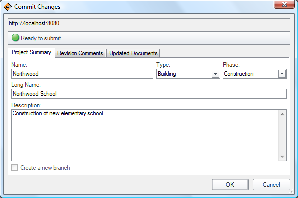 The Project Summary tab is shown by default for new projects, where new or updated summary information about the project may be entered. This information is displayed in the server list, and is also reflected on the main Project object. To create a new branch of the current project (or branch), check the Create a New Branch checkbox, where the new branch will take on the specified project summary information. 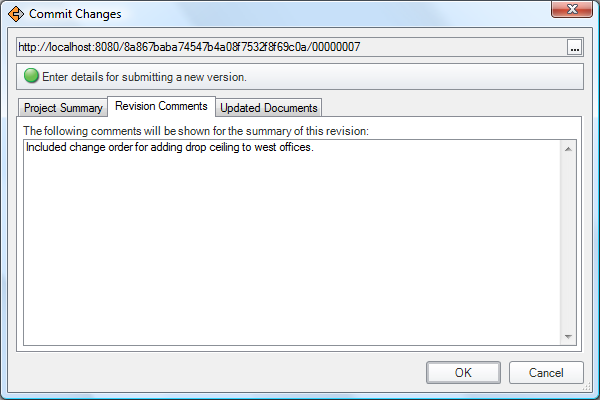 The Revision Comments tab is shown by default for existing projects, where a summary of changes specific to the revision may be entered. This information is displayed in the version list for this project or branch, and is also reflected in a Library Information record within the project. To merge a branch back into the parent branch, click the browse button on the top-right of the URL box and select the branch for which to submit. The Updated Documents tab shows any attached files that will be uploaded to the server upon checkin. Clicking OK attempts to submit the project changes to a model server and publishes a new version. If the submission is rejected such as due to merge conflicts or other violations, a message box will be displayed providing instructions. |
The Email menu supports sending the current project over email. The menu pane lists project participants for which to send email.
| Command | Description |
 Send Attachment |
Launch the default email program to send the current project as a file attachment. This button is enabled if the window has an active project. |
 Send Link |
Launch the default email program to send a link to the current project on a model server. This button is enabled if the window has an active project that has been published to a model server (indicated by the project having an associated Library). |
The Print menu supports printing the current view. The menu pane displays a preview of what will be printed.
| Command | Description |
 |
Print the active view to the default printer as shown in the preview. This button is enabled if the window has an active project. |
 Print To |
Launches the Print Dialog to print to a specific printer with specified settings. This button is enabled if the window has an active project. |
The Info menu supports viewing data details of the current project. The menu pane displays the raw data content which may be navigated by expanding object references.
| Command | Description |
 File Compatibility |
Launches a dialog for selecting the active IFC schema version and optional Model View Definition, to constrain the application to support a subset of data. |
 Redact For User |
Launches a dialog for selecting a user, and removes all information for which the user does not have access permission to read. |
The Options menu supports customizing user preferences. The menu pane displays objects and properties specific to the current Windows user profile, including default model servers and accounts.
| Command | Description |
 Reset Options |
Resets options to default values, as displayed in the grid. This button is always enabled. |
 Activate License |
Launches the License Dialog to view the license status, activate, deactivate, or reactivate a license on the current machine.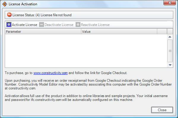 After purchasing Constructivity Model Editor, a license can be activated on the current machine by clicking the Activate License button. This will launch a dialog for entering the Order Number from Google Checkout. 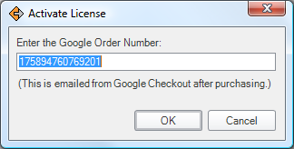 Enter the order number (copy and paste to avoid mistakes) and click OK. The application will then contact constructivity.com and download a license for the specified order number. Within a few seconds, the application should be activated. A license can be effectively transfered to another machine by deactivating a license on one machine and activating (or reactivating) a license on another machine. A license can be reactivated on the same machine by clicking Reactivate License. License information is stored in the local Windows application settings directory for Constructivity. |
The Help menu provides documentation and links to support.
| Command | Description |
 Help |
Launch the help file providing documentation. This button is always enabled. |
 Website |
Launch the www.constructivity.com website in the default web browser. This button is always enabled. |
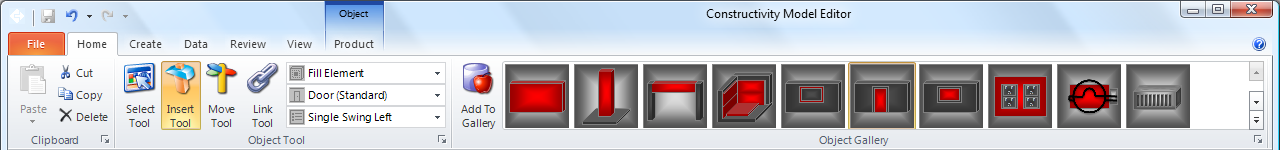
Home Ribbon
The Home Ribbon contains the most common functionality for editing projects.
The Clipboard ribbon bar supports functionality for moving, copying, and deleting objects.
| Command | Description |
 Paste |
Pastes the clipboard item within the current selection. In Item View, enters placement mode to position the item at the location of the cursor. |
 Cut |
Cuts the current selection and places it on the clipboard. This has the same effect as Copy followed by Delete. |
 Copy |
Copies the current selection and places it on the clipboard. The clipboard may hold multiple items, where the most recently copied item is used for pasting. The Clipboard Pane may be displayed using the Clipboard Launcher button for setting the active clipboard item. |
 Delete |
Deletes the current selection. Any dependent objects are also deleted. Upon deleting, the selection changes to the hosting object where delete may be used successively. For example, deleting a Door will remove the door but keep the Opening intact which also be deleted. Similarly, duct segments and fittings can be successively deleted following the chain of connections. |
| Clipboard Launcher | Shows or hides the Clipboard Pane for recalling multiple items on the clipboard. |
The Object Tool ribbon bar changes the current editing mode.
| Command | Description |
 Select |
Select items by clicking, and drag/drop to other workspaces.
Available relationships include:
|
 Insert |
Insert new objects by clicking to place and optionally dragging to position. The Group Workspace supports the following relationships:
The Product Workspace supports the following relationships:
The Process Workspace supports the following relationships:
The Resource Workspace supports the following relationships:
|
 Link |
Link objects by clicking on the source and dragging to the target. The Product Workspace provides the following relationships:
|
 Move |
Move objects by clicking and dragging to position. The Group Workspace provides the following usage:
The Product Workspace provides the following usage:
The Process Workspace provides the following usage:
|
 Relation Type |
Indicates the relationship to use when selecting, inserting, linking, or moving objects. The available relationships depend on the current container of the active Workspace and the current Tool Mode. |
 Object Type |
Indicates the type of the target object to use when inserting or linking objects. |
 Usage Type |
Indicates the usage (or subtype) of the target object to insert or link. |
| Tool Launcher | Launches the Tool Dialog for selecting relationship types, object types, and usage types from a graphical view. |
The Gallery ribbon bar contains customizable presets for quickly indicating product types and templates to use. The contents are specific to the type of the current container.
| Command | Description |
 Add To Gallery |
Adds a new gallery preset using the current Type and Template settings.
This allows commonly used tools and product types to be instantly accessable. Gallery presets are specific to the current Tool and type of container. For example, default presets for Site include Building and Geographic Element; default presets for Building Storey include Wall, Door, and Window elements. Gallery presets are not recorded within the current project, but saved as a user preference. Items can be removed or re-ordered within the gallery using the Dialog Launcher button. |
| Gallery Launcher | Launches the Gallery Dialog for customizing, removing, or re-ordering items. |
Create Ribbon
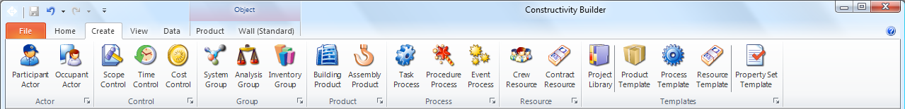
Each ribbon bar has a launcher button which displays the Workspace tab where corresponding objects are created.
The Actor ribbon bar is used to declare people and organizations.
| Command | Description |
 Project Actor |
Creates a person or organization involved in the project.
Project actors may be composed by the following:
|
 Occupant Actor |
Creates a person or organization to occupy a building or space.
Project actors may be composed by the following:
|
The Control ribbon bar is used to declare requirements and track scope, time, cost, or quality.
| Command | Description |
 Scope Control |
Creates a project order to encompase a scope of work. Project orders may be composed by the following:
|
 Time Control |
Creates a work plan for tracking activities over time. Work plans may be composed by the following:
|
 Cost Control |
Creates a cost item, consisting of a breakdown of costs for a project. Costs items may be composed by the following:
|
 Quality Control |
Creates performance history for predicting or recording actual conditions over time. Performance history may be composed by the following:
|
The Group ribbon bar is used to declare systems, analysis models, and other groups.
| Command | Description |
 System Group |
Creates a system group for building systems, distribution systems, and zones. System groups may be composed by the following:
|
 Analysis Group |
Creates a structural analysis model. Analysis models may be composed by the following:
|
 Inventory Group |
Creates an inventory group. Inventories may be composed by the following:
|
The Product ribbon bar is used to declare building structures.
| Command | Description |
 Site Product |
Creates a building site reflecting a geographic location and boundaries. Sites may be composed by the following:
|
 Building Product |
Creates a standalone building without any site defined. Buildings may be composed by the following:
|
The Process ribbon bar is used to declare tasks, procedures, and events in time.
| Command | Description |
 Event Process |
Creates an event which defines a condition for triggering processes. Events may be composed by the following:
|
 Procedure Process |
Creates a procedure which defines an arbitrary process. Procedures may be composed by the following:
|
 Task Process |
Creates a task which defines a scheduled process. Tasks may be composed by the following:
|
The Resource ribbon bar is used to declare internal and external resources.
| Command | Description |
 Crew Resource |
Creates a crew resource for materials, labor, and equipment under internal control. Crew resources may be composed by the following:
|
 Contract Resource |
Creates a subcontract resource for products or services under external control. Subcontract resources may be composed by the following:
|
The Template ribbon bar is used to declare object type definitions.
| Command | Description |
 Project Library |
Attaches a project library containing referenced templates for products, processes, resources, or properties. A wizard is launched for selecting project libraries. |
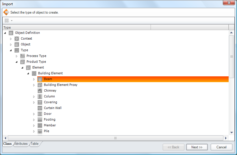
 Product Template |
Creates a product type such as indicating a product model. A wizard is launched for specifying the particular type and source of data (see below). |
 Process Template |
Creates a process type such as indicating shared construction procedures. A wizard is launched for specifying the particular type and source of data (see below). |
 Resource Template |
Creates a resource type such as indicating shared resource productivity. A wizard is launched for specifying the particular type and source of data (see below). |
 Property Template |
Creates a property set template for indicating details on objects of particular types. A wizard is launched for specifying the particular type and applicable entity. |
Upon clicking a button to create an object, a wizard is displayed consisting of multiple steps.
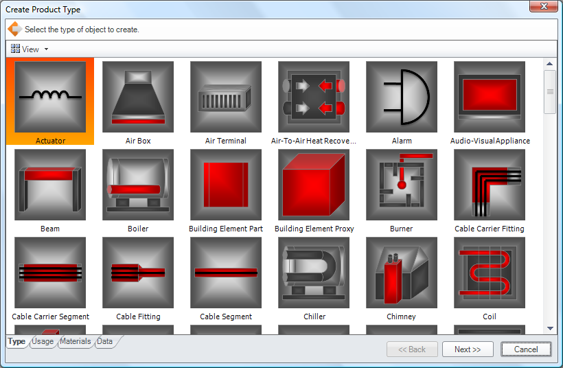
The wizard contains multiple tabs for each step, where the Next button advances to the next step and the Back button goes to the previous step. A choice made in an earlier step often determines options available in later steps. In the table below, an asterisk indicates dependent steps.
| Step | Description |
| Type | Indicate the object type to create. |
| Usage | Indicate the usage type (or subtype) to create. |
| Materials* | Indicate material constituents, layers, or profiles. [Product Templates] |
| Data | Indicate an optional external source of data, or finish the wizard. |
| Classification* | Indicate a classification to import. [Data indicates classification type] |
| Document* | Indicate a document to import. [Data indicates document type] |
| Library* | Indicate a library to import. [Data indicates library type] |
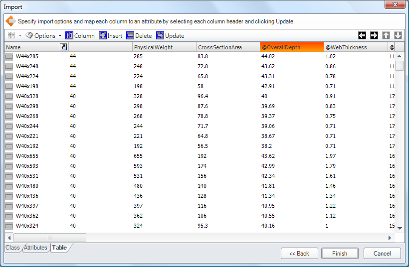
| Aspects* | Indicate rows and columns to import. [Data indicates generic format] |
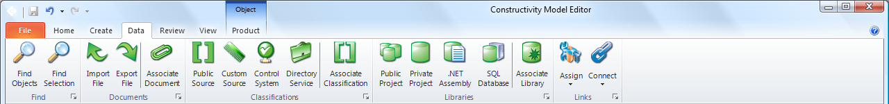
Data Ribbon
The Data Ribbon contains functions for importing, exporting, and synchronizing data from other sources.
The Find ribbon bar is used for finding objects of certain types within the project.
| Command | Description |
 Find Objects |
Launches a dialog for selecting an object type according to inheritance hierarchy. Items of the selected type are then displayed in the Find Pane. |
 Find Selection |
Filters the Find Pane to show items of the same type as the current selection. Items of the same type are then displayed in the Find Pane. |
| Launcher | Shows the Find Pane. |
The Documents ribbon bar is used to import, export, or attach files to the project.
| Command | Description |
 Import File |
Imports a file and optionally keeps references to the file for data synchronization.
Launches a File Open dialog for choosing the file type and file.
Supported file formats for import include:
If the project is published to a model server, the document will be uploaded with the next checkin. |
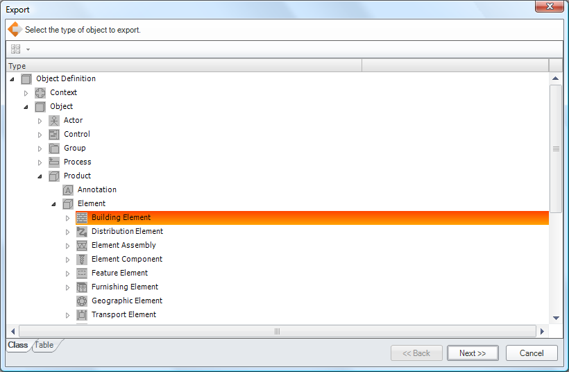
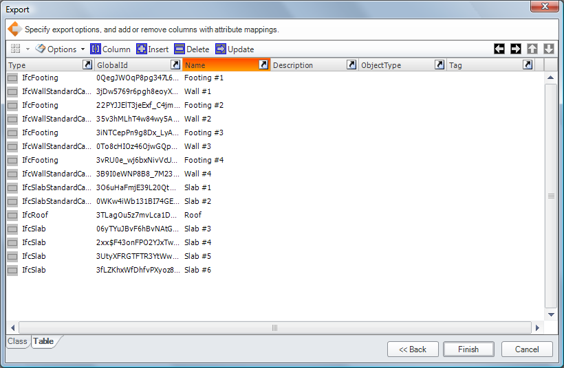
 Export File |
Exports a file and optionally keeps references to the file for data synchronization.
Launches a File Save dialog for choosing the file type and file.
Supported file formats for export include:
Microsoft Excel files are formatted with the first worksheet containing header information, and additional worksheets for each mapped type. Each worksheet has a single header row with cells identifying each field. Each cell is formatted with the value of the attribute as follows:
|
 Attach File |
Attaches an arbitrary file to the project, linked to the current selection by default.
If the project is published to a model server, the document will be uploaded with the next checkin. If connected to a Constructivity Server Enterprise Edition, the server can be configured to automatically synchronize data within attached files. Supported file formats for synchronization include:
|
| Launcher | Filters the Find Pane and Links Pane to show document information. |
The Classifications ribbon bar is used to import, create, or link classifications within the project.
| Command | Description |
 Public Classification |
Launches a dialog for choosing industry classification sources to use for the current project.
Standard classification sources include:
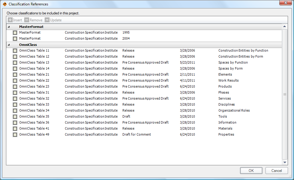 |
 Custom Classification |
Creates a custom classification for the project, and launches the Object Dialog for editing. |
 Control System |
Launches a dialog for choosing system classification sources to use for the current project.
System classifications are hosted by specialized servers or control devices.
The available systems vary according to the Constructivity Server edition, which may include:
|
 Directory Service |
Launches a dialog for selecting users, organizations, or other items from the Windows Active Directory service.
Users linked to Active Directory inherit permissions and group memberships defined within the Windows security environment.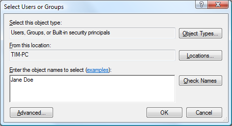 |
| Launcher | Filters the Find Pane and Links Pane to show clasification information. |
The Libraries ribbon bar is used to reference content from other projects.
| Command | Description |
 Public Libraries |
Launches a dialog for referencing external projects published on constructivity.com. The dialog lists public projects available on the model server. Selecting a project attaches a reference such that items within the referenced project are available to the current project. |
 Private Libraries |
Launches a dialog for referencing external projects from a private model server specific to an organization or individual. The dialog lists public projects available on the model server. Selecting a project attaches a reference such that items within the referenced project are available to the current project. |
 .NET Assembly |
Imports a process template library from a .DLL file representing a programmable .NET assembly. This may be used to integrate custom behaviors for control systems or operational schedules. Each public .NET class corresponds to a task type containing property sets, procedure types, and event types. |
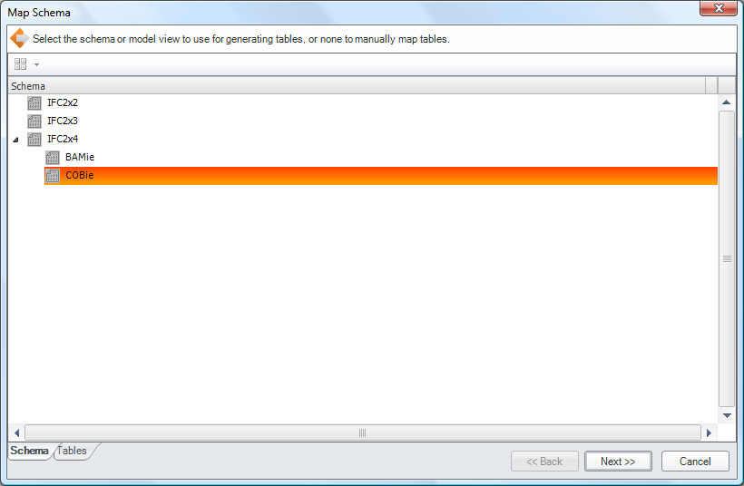
 SQL Database |
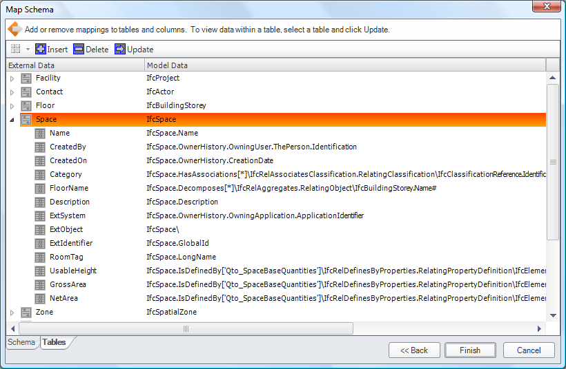
Connects the project to a SQL database where data is synchronized in both directions. 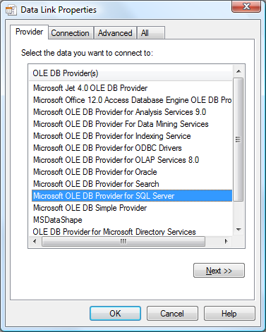 A wizard follows for customizing how data is mapped:
Upon submitting changes to Constructivity Server Enterprise Edition, data is synchronized in both directions as changes are made. Note that the database connection string established from the local computer must also be accessible from the server computer. |
| Launcher | Filters the Find Pane and Links Pane to show library information. |
The Links ribbon bar is used to set relationships between the selected object and other objects.
| Command | Description |
 Assignment |
This dropdown button provides commands for creating assignment relationships.
|
 Connection |
This dropdown button provides commands for creating connection relationships.
|
| Launcher | Launches the Links Pane of the Object Dialog to navigate relationships of the selected object. |
Review Ribbon
The Review Ribbon contains functions for validating, approving, comparing, and tracking changes.
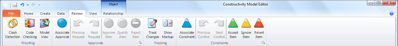
The Proofing ribbon bar is used to check the project against rules and generate applicable constraints.
| Command | Description |
 Clash Detection |
Detects geometric collisions between elements and generates interference relationships. A collision occurs if the 'Body' representation of one element intersects with the 'Body' or 'Clearance' representations of another element. Clash detection operations occur in the background, and upon completion generate interaction relationships displayed in the Find Pane. |
 Code Checking |
Checks the project for building code violations. Launches a dialog for selecting the applicable building codes to validate. |
 Model View |
Checks the project for conformance with a Model View Definition.
A wizard follows for selecting the model view and exchange:
|
The Approvals ribbon bar is used to navigate open approvals.
| Command | Description |
 Previous Request |
Navigates to the previous approval request, without taking any action on the current item. This button is enabled if at least one request has been skipped. |
 Next Request |
Navigates to the next approval request, without taking any action on the current item. This button is enabled if at least one request follows. |
 Approve Item |
Approves the current item and navigates to the next item. |
 Qualify Item |
Marks conditional approval on the current item, launching a dialog to specify conditions, and navigates to the next item. |
 Reject Item |
Rejects the current item, launching a dialog to specify rationale, and navigates to the next item. |
| Launcher | Launches the Find Pane filtered to show all approvals within the project. |
The Tracking ribbon bar is used to record and/or display changes for the current project revision.
| Command | Description |
|
Track Changes |
If checked, indicates that changes are to be tracked, such that previous values may be compared later. |
|
Show Markup |
If checked, indicates that changes are to be indicated in all views.
The following color conventions apply:
|
The Constraints ribbon bar is used to navigate open conflicts.
| Command | Description |
 Previous Confict |
Navigates to the previous constraint conflict, without taking any action on the current item. This button is enabled if at least one conflict has been skipped. |
 Next Conflict |
Navigates to the next constraint conflict, without taking any action on the current item. This button is enabled if at least one conflict follows. |
 Accept Item |
Accepts the current value and navigates to the next item. For merge conflicts, this indicates using the local value. |
 Ignore Item |
Marks the the constraint to be ignored and navigates to the next item. For merge conflicts, both values are retained and may be resolved later. |
 Revert Item |
Rejects the current value, replacing it with the constrained value. For merge conflicts, this indicates using the value specified by someone else. |
| Launcher | Launches the Find Pane filtered to show all constraints within the project. |
Constraints can be edited to indicate attributes and permitted values. The Constraint Page displays a tree of attributes and corresponding benchmarks.
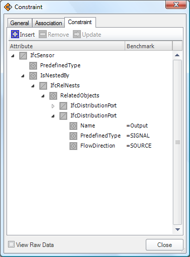
Columns are displayed as follows:
- Name: Indicates the attribute name.
- Benchmark: Indicates the set of operators and values.
- Value: Indicates the actual value on constrained objects, or blank if the value varies among objects.
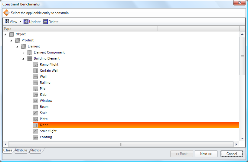
To add a constraint, select the parent attribute or entity reference, click Insert, and follow the steps of the wizard:
- Class: Select the applicable entity which may be the type of the referencing entity or a subtype. This step is skipped when adding attributes to an existing entity reference.
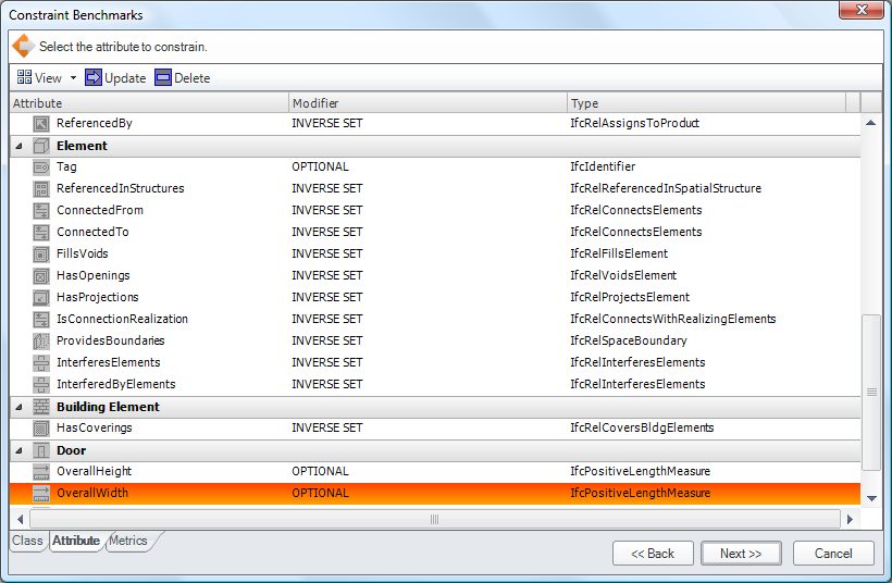
- Attribute: Select the attribute on the applicable entity, which may be a direct attribute or an inverse attribute.
- Metrics: Edit metrics for the attribute.
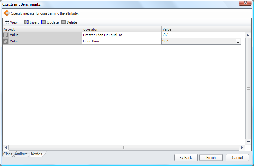
Columns are displayed as follows:- Aspect: Indicates the aspect to compare such as the Value, Type, or Element.
- Operator: Indicate the operator, such as Equal, Not Equal, Greater Than, etc.
- Value: Indicate the value, which may be an explicit value, a formula, a time series, or a table.
The available operator types vary according to the attribute type:
- REAL: All operators are available for floating-point comparison.
- INTEGER: All operators are available for integer comparison.
- BOOLEAN: Equality operators are available.
- LOGICAL: Equality operators are available.
- ENUM: Equality operators are available.
- STRING: All operators are available for string comparison.
- BINARY: All operators are available for binary comparison.
- ENTITY: All operators are available for entity type comparison, where Greater Than indicates subclass and Less Than indicates superclass.
The available value types include:
- Value: An explicit value of the same type as the constrained attribute, using default units.
- Measure: An explicit value using custom units.
- Formula: A formula consisting of a tree of referenced attributes, arithmetic operators, and explicit values.
- Table: A table consisting of supported values, and optional corresponding values for other attributes, such as model lookups having corresponding dimensions.
- Time Series: A set of values scheduled over time, used for animation of attributes such as door swings.
View Ribbon
The View Ribbon allows adjusting how information is displayed.
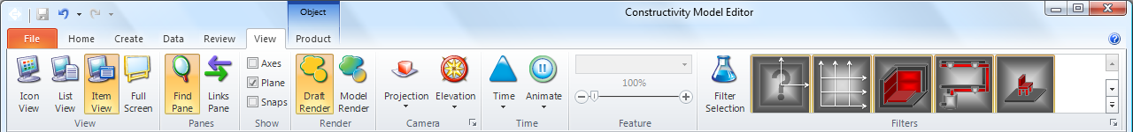
The View ribbon bar switches between viewing modes for the active workspace. The view can also be adjusted using the small buttons on the lower right of the status bar.
| Command | Description |
Icon View |
View objects as icons or thumbnail previews. This view is useful for browsing product types according to graphical image or photo. |
 List View |
View objects in tabular form. This view is useful for browsing objects by detailed summaries. |
 Item View |
View items in graphical detail.
|
 Full Screen |
View in full-screen mode, suitable for presentations, kiosks, or control panels. In full-screen mode, the mouse, keyboard, and remote controls are used for navigation:
|
The Show ribbon bar shows or hides annotations within the current view.
| Command | Description |
| Axes | Check to show X, Y, and Z axes to indicate the position and orientation at the origin. |
| Plane | Check to show the XY plane to indicate the position, orientation, and scale at the base plane. |
| Snaps | Check to show guidelines of the selected object to help determine position and orientation. |
The Camera ribbon bar adjusts 3D angle and projection.
| Command | Description |
 Camera Elevation |
Switches to camera presets including side elevations, corner angles, and overhead plan view.
|
 Camera Projection |
Switches between perspective and isometric projections.
|
 Camera Operation |
Switches between camera navigation modes.
|
The Render ribbon bar changes the current rendering mode.
| Command | Description |
 Draft Render |
Renders items using simplified representations.
|
 Model Render |
Renders items using detailed representations.
|
The Time ribbon bar allows the project to be viewed at a particular point in time.
| Command | Description |
 Time |
View items throughout the entire lifecycle, start, end, or somewhere in between.
|
 Animate |
Show construction sequences progressing through time forwards or backwards.
|
The Filter ribbon bar allows items to be shown or hidden according to type.
| Command | Description |
 Filter Selection |
Includes a filter for the type of the current selection, and sets the filter to off to hide all objects of such type. Filters are useful for accessing objects that are obscured, such as by hiding roofs or coverings. Configured filters vary according to the type of the container object. For example, a Site has filters for Annotations and Grids by default, while a Building has a filter for Roof. The gallery of filters indicates which types are shown or hidden according to the pressed state of the button. Inherited types may be used to show or hide a broad class of objects, where a visible filter takes precedence. For example, all distribution elements may be hidden except for air terminals by having "Distribution Element" turned off and "Air Terminal" turned on. |
| Filter Launcher | Launches the Filter Dialog for adding or removing filters. |
Object Ribbon
The Object Ribbon contains context-sensitive commands that affect the current selection. The available ribbon bars vary according to the object type.
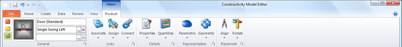
The General ribbon bar is used to set the objet type and template information such as the product model for the selected building product.
| Command | Description |
| Entity | The top textbox indicates the general type of the object and may allow certain objects to be transformed into other entities. |
| Type | The middle textbox indicates the predefined type of the object, for which default settings and geometry are generated, and filters the available templates. The Delete button clears the predefined type, removing any type-specific settings. The Browse button launches a dialog for selecting the predefined type. |
| Template | The bottom textbox indicates the template of the object, which may refer to a product model having explicit geometry or a product style having parametric geometry. The Delete button clears the template, removing any template-specific settings. The Browse button launches a dialog for selecting a template from the current project or referenced projects. |
| Icon | The icon indicates a visual representation of the object, and may be clicked to navigate to change the icon. |
| Launcher |
Launches the General page of the Object Dialog to access general settings, including Name, Description, Identification, Type, History, and Lock State.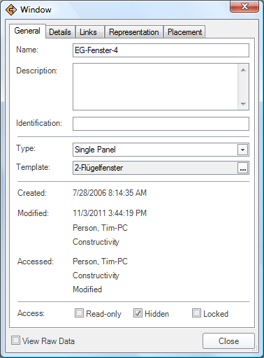 Template usage is specific to various object types as follows:
|
The Access ribbon bar is used to set the lock state, access state, and access permissions for the current selection.
| Command | Description |
 No Access |
Sets the selected workspace object to no access such that it cannot be viewed by others. All descendents inherit this setting unless they have more restrictive access.
This button is enabled if the object is either unlocked or locked by the current user. |
 Read-Only |
Sets the selected workspace object to read-only. All descendents inherit this setting unless they have more restrictive access.
This button is enabled if the object is either unlocked or locked by the current user. |
 Read/Write |
Sets the selected workspace object to read/write. All descendents inherit this setting unless they have more restrictive access.
This is the default setting for all objects. This button is enabled if the object is either unlocked or locked by the current user. |
| Lock | This button may be checked to lock the object such that others may not edit. If enabled and unchecked, it means the object is locked. If enabled and checked, it means the object is locked by you. If disabled and unchecked, it means the project is not connected to a server. If disabled and checked, ite mean the object is locked by someone else. |
| Launcher |
Launches the Access Page of the Object Dialog for configuring permissions on the object.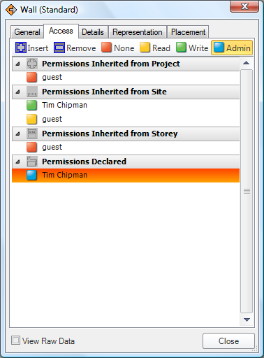 The list displays permissions explicitly declared on the current object in addition to permissions inherited from containing objects. The toolbar contains the following buttons:
|
The Details ribbon bar is used to set properties and quantities of the selected object.
| Command | Description |
 Properties |
This dropdown button provides commands for adding and removing property sets for the current object and descendent objects. Properties are specified by the user and in some cases may be used to generate product geometry. |
 Quantities |
This dropdown button provides commands for adding and removing quantity sets for the current object and descendent objects. Quantities are automatically calcalated according to product geometry and materials. Task durations and costs may be calculated according to resource productivity applied to quantities of resulting building products. |
| Launcher |
Launches the Details page of the Object Dialog to access properties and quantities.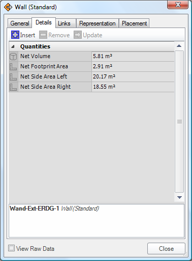
|
The Representation ribbon bar is used to edit solid geometry, parametric curves, parametric surfaces, annotations, and other representations.
| Command | Description |
 Material |
This dropdown button provides commands for editing materials of product representations.
|
 Geometry |
This dropdown button provides commands for editing geometry of product representations, which enters a mode for editing.
|
| Launcher |
Launches the Representations page of the Object Dialog to access details of geometry and styles.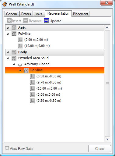
|
The Placement ribbon bar is used to edit the position and orientation of the selected object.
| Command | Description |
 Align |
This dropdown button provides commands for aligning the object with other objects in various directions.
|
 Rotate |
This dropdown button provides commands for rotating the object.
|
| Launcher |
Launches the Placement page of the Object Dialog to access details of position, orientation, and grid intersections.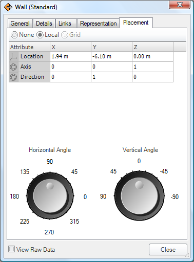
|
Representation Ribbon
The Representation Ribbon supports editing shapes of products or product types. It is activated upon entering edit mode using Parametric or Geometric menus from the Object Ribbon representation bar.
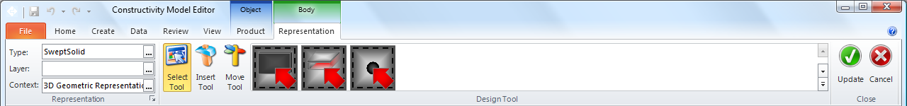
The Representation ribbon bar is used to change the shape type, layer, aspect, and style for the selected geometry.
| Command | Description |
| Type |
The top textbox indicates the type of the object and may allow certain shapes to be transformed into other shape types.
|
| Layer |
The middle textbox indicates the presentation layer of the shape, if applicable.
|
| Aspect |
The bottom textbox indicates the shape aspect of the object, which may refer to the name of a material constituent, layer, or profile to indicate a parametric definition.
|
| Launcher | Launches the Representation Dialog to view or edit the geometry hierarchy. |
The Representation Tool ribbon bar changes the current editing mode.
| Command | Description |
Select |
Select shapes by clicking. Available selection types vary according to the representation type and include:
|
Insert |
Insert new shapes by clicking to place and optionally dragging to position. Available shape types vary according to the representation type as follows:
|
Move |
Move shapes by clicking and dragging to position. Available operations include:
|
The Close ribbon bar is used to exit representation editing mode.
| Command | Description |
| Update | The update button exits representation editing mode, committing changes to the object. |
| Revert | The revert button exits representation editing mode, discarding any changes to the object. |
Point Ribbon
The Point Ribbon supports editing cartesian points in 2D or 3D. It is activated upon entering edit mode using the Geometry menu from the Object Ribbon representation bar, and selecting geometry within the view.
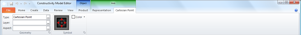
The Geometry ribbon bar is used to change the shape type, layer, and aspect for the selected geometry.
| Command | Description |
| Type | The top textbox indicates the type of the object and may allow certain shapes to be transformed into other shape types. Clicking the button Launches a dialog for selecting the shape type. |
| Layer | The middle textbox indicates the presentation layer of the shape, if applicable. Clicking the button launches a dialog for selecting the presentation layer. |
| Aspect | The bottom textbox indicates the shape aspect of the object, which may refer to the name of a material constituent, layer, or profile to indicate a parametric definition. Clicking the button launches a dialog for selecting the shape aspect. |
| Launcher |
Launches the Geometry Page of the Item Dialog to view or edit the geometry, styles, positioning, and other attributes. 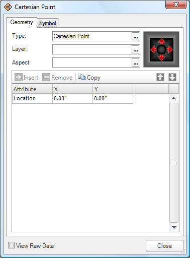
|
The Symbol ribbon bar edits the symbol style.
| Command | Description |
| Symbol | Launches a dialog to apply an existing symbol style to the selected item. |
| Color | Sets the color of the symbol style for the selected item. |
| (Launcher) |
Launches the Symbol page of the Item Dialog to access specific attributes of the symbol style.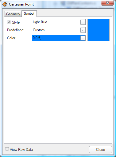
|
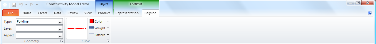
Curve Ribbon
The Curve Ribbon supports editing 2D and 3D curves, including polylines, arcs, splines, and composite curves. It is activated upon entering edit mode using the Geometry menu from the Object Ribbon representation bar, and selecting geometry within the view.
The Geometry ribbon bar is used to change the shape type, layer, and aspect for the selected geometry.
| Command | Description |
| Type | The top textbox indicates the type of the object and may allow certain shapes to be transformed into other shape types. Clicking the button Launches a dialog for selecting the shape type. |
| Layer | The middle textbox indicates the presentation layer of the shape, if applicable. Clicking the button launches a dialog for selecting the presentation layer. |
| Aspect | The bottom textbox indicates the shape aspect of the object, which may refer to the name of a material constituent, layer, or profile to indicate a parametric definition. Clicking the button launches a dialog for selecting the shape aspect. |
| Launcher |
Launches the Geometry Page of the Item Dialog to view or edit the curve geometry. 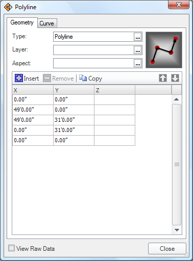
|
The Curve ribbon bar edits the curve style.
| Command | Description |
| Style | Launches a dialog to apply an existing curve style to the selected item. |
| Color | Sets the color of the curve style for the selected item. |
| Weight | Sets the weight of the curve style for the current selection. |
| Pattern | Sets the pattern of the curve style for the current selection. |
| Launcher |
Launches the Curve page of the Item Dialog to access specific attributes of the curve style.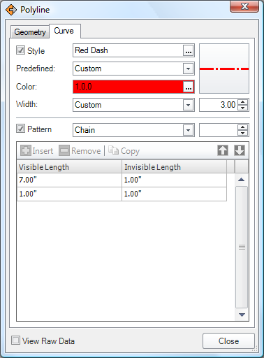
|
Area Ribbon
The Area Ribbon supports editing 2D areas, for footprint, profile, and annotation representations. It is activated upon entering edit mode using the Geometry menu from the Object Ribbon representation bar, and selecting geometry within the view.
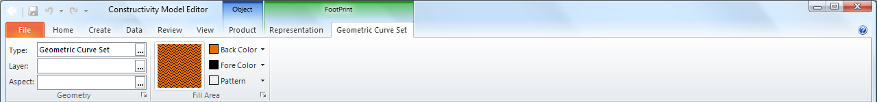
The Geometry ribbon bar is used to change the shape type, layer, and aspect for the selected geometry.
| Command | Description |
| Type | The top textbox indicates the type of the object and may allow certain shapes to be transformed into other shape types. Clicking the button Launches a dialog for selecting the shape type. |
| Layer | The middle textbox indicates the presentation layer of the shape, if applicable. Clicking the button launches a dialog for selecting the presentation layer. |
| Aspect | The bottom textbox indicates the shape aspect of the object, which may refer to the name of a material constituent, layer, or profile to indicate a parametric definition. Clicking the button launches a dialog for selecting the shape aspect. |
| Launcher |
Launches the Geometry Page of the Item Dialog to view or edit the shape. 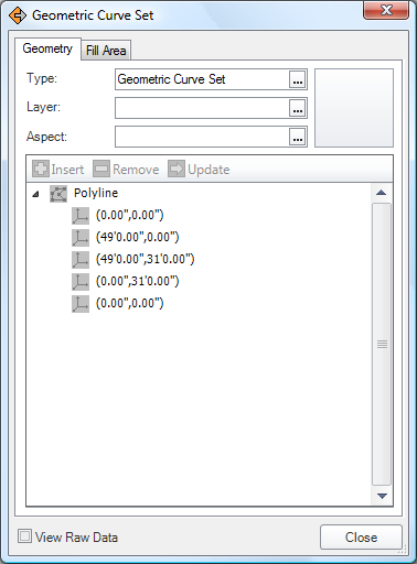
|
The Area ribbon bar edits the fill area style.
| Command | Description |
| Style | Launches a dialog to apply an existing fill area style to the selected item. |
| Fore Color | Sets the foreground color of the fill area style for the selected item. |
| Back Color | Sets the background color of the fill area style for the selected item. |
| Pattern | Sets the pattern of the fill area style for the current selection. |
| Launcher |
Launches the Fill Area page of the Item Dialog to access specific attributes of the fill area style.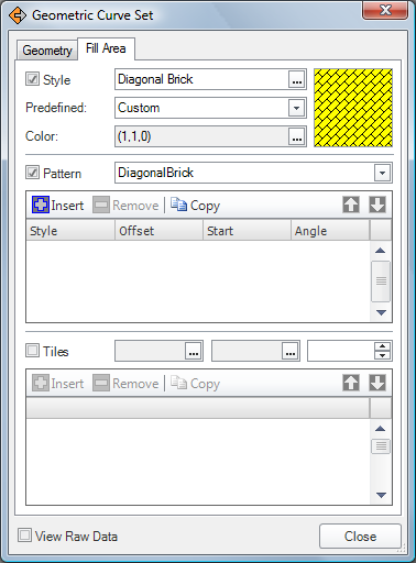
|
Surface Ribbon
The Surface Ribbon supports editing geometry. It is activated upon entering edit mode using the Geometry menu from the Object Ribbon representation bar, and selecting geometry within the view.
The Geometry ribbon bar is used to change the shape type, layer, and aspect for the selected geometry.
| Command | Description |
| Type | The top textbox indicates the type of the object and may allow certain shapes to be transformed into other shape types. Clicking the button Launches a dialog for selecting the shape type. |
| Layer | The middle textbox indicates the presentation layer of the shape, if applicable. Clicking the button launches a dialog for selecting the presentation layer. |
| Aspect | The bottom textbox indicates the shape aspect of the object, which may refer to the name of a material constituent, layer, or profile to indicate a parametric definition. Clicking the button launches a dialog for selecting the shape aspect. |
| Launcher |
Launches the Geometry Page of the Item Dialog to view or edit the geometry, styles, positioning, and other attributes. 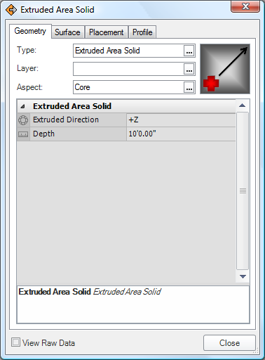
|
The Surface ribbon bar edits the surface style.
| Command | Description |
| Style | Launches a dialog to apply an existing surface style to the selected item. |
| Color | Sets the color of the surface style for the selected item. |
| Reflectance | Sets the reflectance effect of the surface style for the selected item. |
| Texture | Sets the texture of the surface style for the current selection. |
| (Launcher) |
Launches the Surface page of the Item Dialog to access specific attributes of the surface style.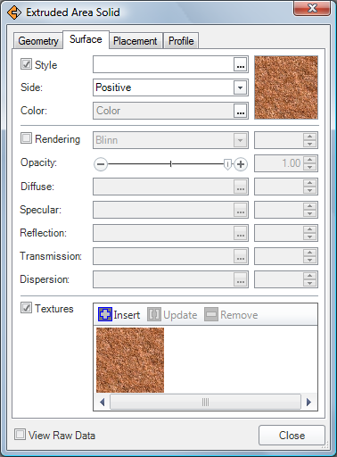
|
The Placement ribbon bar is used to edit the location and rotation of the selected item.
| Command | Description |
| Align | Provides commands for positioning the selected item. |
| Rotate | Provides commands for rotating the selected item. |
| (Launcher) |
Launches the Placement page of the Item Dialog to specify precise positioning and rotation of the selected item.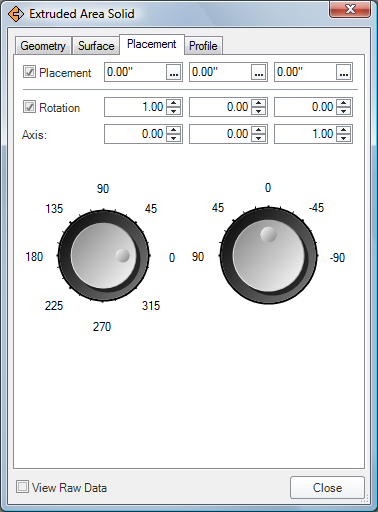
|
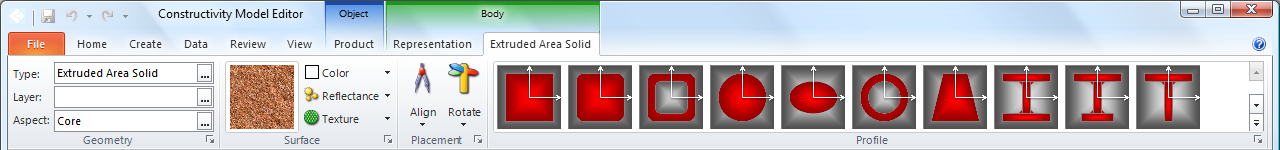
The Profile ribbon bar is used to edit the profile of the selected item (applicable on swept solids and swept surfaces).
| Command | Description |
| Gallery | Click on a profile type to apply the shape to the selected item. |
| (Launcher) |
Launches the Profile page of the Item Dialog to specify precise positioning and rotation of the selected item.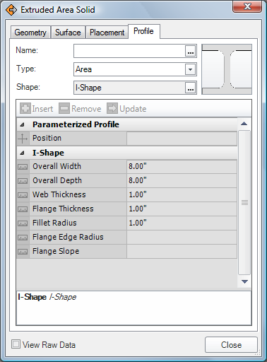
|
Text Ribbon
The Text Ribbon supports editing text for annotations. It is activated upon entering edit mode using the Geometry menu from the Object Ribbon representation bar, and selecting geometry within the view.
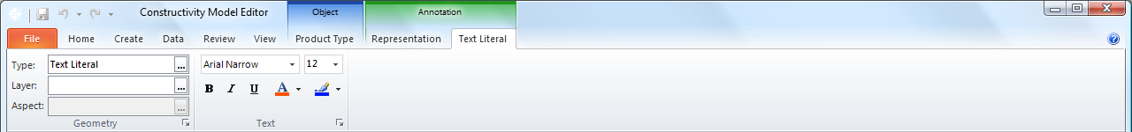
The Geometry ribbon bar is used to change the shape type, layer, and aspect for the selected geometry.
| Command | Description |
| Type | The top textbox indicates the type of the object and may allow certain shapes to be transformed into other shape types. Clicking the button Launches a dialog for selecting the shape type. |
| Layer | The middle textbox indicates the presentation layer of the shape, if applicable. Clicking the button launches a dialog for selecting the presentation layer. |
| Aspect | The bottom textbox indicates the shape aspect of the object, which may refer to the name of a material constituent, layer, or profile to indicate a parametric definition. Clicking the button launches a dialog for selecting the shape aspect. |
| Launcher |
Launches the Geometry Page of the Item Dialog to view or edit the text and formatting.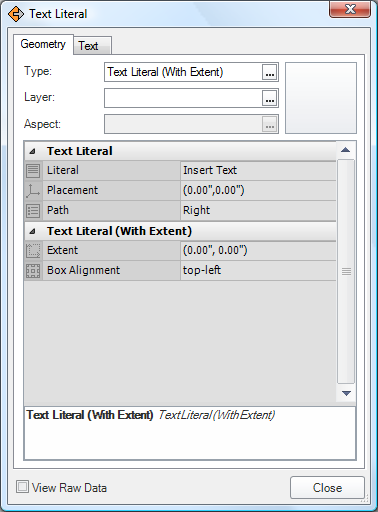
|
The Text ribbon bar edits the text style.
| Command | Description |
| Text | Launches a dialog to apply an existing text style to the selected item. |
| Fore Color | Sets the foreground color of the fill area style for the selected item. |
| Back Color | Sets the background color of the fill area style for the selected item. |
| Font | Sets the font of the text style for the current selection. |
| (Launcher) |
Launches the Text page of the Item Dialog to access specific attributes of the text style.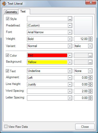
|
Spatial Elements
Spatial elements include sites, buildings, storeys, spaces (rooms), and annotations.
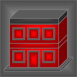 Building Building |
A Building may be inserted within a Site or may be created as a top-level object from Create - Spatial Element. By default, a building is created with a rectangular footprint, a single storey containing a single space, concrete slab, exterior walls, and a hipped roof. To edit the footprint, switch to Design Mode; use the Move tool to move vertices or split segments. Click on a point and drag to open space to move the point, or drag onto another point to combine segments in between. Click on a segment and drag to split the segment into two, and drag the resulting point to move its position. Upon modifying the footprint, the slab, exterior walls, and roof will be regenerated. To edit the interior of a building drill into a storey using the container tree bar above the 3D view. A building may contain Building Storeys which may be added using the Insert tool or removed by using the Select tool to select and delete a storey. |
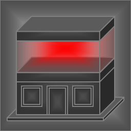 Building Storey Building Storey |
A Building Storey may be inserted within a Building using the Insert tool and clicking on an existing storey where it is to be inserted above. Upon inserting a storey, existing storeys will be shifted upwards. A storey may be deleted by navigating to the enclosing Building (using the container tree bar above the 3D view), selecting and clicking Delete. Deleting a storey will shift any storeys above downwards. Storeys are the primary container of building elements where walls, doors, windows, fixtures, etc. may be inserted. |
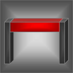
 Site Site |
A Site is a top-level object that may be created from Create - Spatial Element.
A site is defined by a boundary footprint and elevation contours. By default, a site is created with a rectangular footprint and flat elevation. To edit the contour, switch to Design Mode; use the Select tool to pick existing vertices or curves to adjust using the property grid, use the Insert tool to add elevation points; use the Move tool to move vertices, move elevation points, or split segments. A site may contain Buildings or any element directly. |
 Space Space |
A space may be inserted within a Building Storey using the Insert tool, or may be inserted automatically by connecting walls to form an enclosed region.
A space is defined by a boundary footprint which may be edited similar to building footprints. A space may have Coverings for floors, walls, or ceilings using the Insert Tool set to Cover Space / Covering / Flooring (or other subtype). A space may directly contain Furniture; all other elements are placed relative to the containing Building Storey. |
Building Elements
Building elements include walls, slabs, doors, windows, beams, columns, stairs, and more.
 Beam Beam |
A beam may be inserted within a spatial structure (usually a Building Storey) or created automatically such as a lintel over a window opening. To insert a beam, in Object Mode choose the Insert Tool set to Contain Element / Beam. Upon placing, click on the position of one end (which may be on an existing beam or column for which to connect), and drag to either to another beam or column to connect or over the base slab for which to project a cantilever beam, and release the mouse button. A beam may have connections to other beams or columns. A beam may have Structural Curve Members assigned for structural analysis idealization. |
 Column Column |
A column may be inserted within a spatial structure (usually a Building Storey). To insert a column, in Object Mode choose the Insert Tool set to Contain Element / Column. Upon placing, move the mouse over a Slab or Plate and click to insert at the position of the mouse. By default, columns are created vertically with height extending to the building storey or roof above. A column may have connections to beams or other columns. A column may have Structural Curve Members assigned for structural analysis idealization. |
 Covering Covering |
A covering may be inserted within a Space or directly on a building element. To insert a covering, in Object Mode choose the Insert Tool set to Cover Space / Covering / Flooring (or other subtype). Upon placing, move the mouse over a Space and click to insert. A covering will be created at the floor, bounding walls, or ceiling of the space according to the type of covering. If any covered walls or slabs have openings, then corresponding openings are also made in the covering automatically. |
 Door Door |
A door may be inserted within a Wall. To insert a door, in Object Mode choose the Insert Tool set to Fill Element / Door / Single Swing Left (or other subtype). Upon placing, move the mouse to a position along a Wall and click to insert. An opening will be created within the wall for which the door fills. |
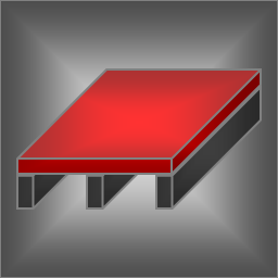 Slab Slab |
A slab may be inserted within a spatial structure (usually a Building Storey), or may be created automatically as part of a building storey, roof, stair, or ramp. To insert a slab, in Object Mode choose the Insert Tool set to Contain Element / Slab. Upon placing, click on the position of one corner, drag to the other corner, and release the mouse button. By default, a slab is created with a rectangular footprint. To edit the footprint, switch to Design Mode; use the Move tool to move vertices or split segments. Click on a point and drag to open space to move the point, or drag onto another point to combine segments in between. Click on a segment and drag to split the segment into two, and drag the resulting point to move its position. Upon modifying the footprint, any conflicting openings will be removed. A slab may contain Openings such as for staircases. A slab may have a Structural Surface Member assigned for structural analysis idealization. |
 Wall Wall |
A wall may be inserted within a spatial structure (usually a Building Storey), or exterior walls may be created automatically as part of a building storey. To insert a wall, in Object Mode choose the Insert Tool set to Contain Element / Wall. Upon placing, click on the position of one end (which may be on a slab or adjacent to an existing wall for which to connect), drag to the other end (which also may connect to an existing wall), and release the mouse button. If connections were made to other walls, then a Space will automatically be generated for any newly enclosed region. A wall may contain Openings optionally filled by elements such as doors, windows, junction boxes, light fixtures, and air terminals. A slab may have a Structural Surface Member assigned for structural analysis idealization. |
 Window Window |
A window may be inserted within a Wall. To insert a window, in Object Mode choose the Insert Tool set to Fill Element / Window. Upon placing, move the mouse to a position along a Wall and click to insert. By default, a window is created with a rectangular profile. To edit the profile, switch to Design Mode; use the Move tool to move vertices or split segments. Click on a point and drag to open space to move the point, or drag onto another point to combine segments in between. Click on a segment and drag to split the segment into two, and drag the resulting point to move its position. |
Structural Elements
Structural elements include footings, piles, and reinforcing.
 Footing Footing |
A footing may be inserted within a spatial structure (usually a Building). To insert a footing, in Object Mode choose the Insert Tool set to Contain Element / Footing. Upon placing a footing, click on the position of one end (which may be on an existing footing or pile for which to connect), and drag to either to another footing or pile to connect or over the site to position the other end, and release the mouse button. A footing may have connections to other footings, slabs, or walls. A footing may have Structural Curve Members assigned for structural analysis idealization. |
 Pile Pile |
A pile may be inserted within a spatial structure (usually a Building). To insert a pile, in Object Mode choose the Insert Tool set to Contain Element / Footing. Upon placing a pile, move the mouse over a Site and click to insert at the position of the mouse. By default, piles are created vertically extending below to a nominal depth. A pile may have connections to footings or columns. A pile may have Structural Curve Members assigned for structural analysis idealization. |
Mechanical Elements
Mechanical elements include equipment for heating, ventilation, and air conditioning (HVAC).
 Air Terminal Air Terminal |
An air terminal may be inserted within a Covering, such as a ceiling, flooring, or wall covering. To insert an air terminal, in Object Mode choose the Insert Tool set to Fill Element / Air Terminal. Upon placing, move the mouse over a Covering and click to place at the indicated position. An air terminal may have a port connection for air conditioning leading from a duct segment. Tip: to more easily access spaces or insides of walls, coverings may be shown or hidden according the filter from the View ribbon. |
 Boiler Boiler |
A boiler may be inserted on top of a Slab. To insert a boiler, in Object Mode choose the Insert Tool set to Contain Element / Boiler. Upon placing, move the mouse over a Slab and click to place at the indicated position. A water boiler has port connections for three pipes (domestic cold water in, domestic hot water out, gas in) and one duct (exhaust out). A steam boiler has port connections for three pipes (heating in, heating out, gas in) and one duct (exhaust out). |
 Chiller Chiller |
A chiller may be inserted on top of a Slab. To insert a chiller, in Object Mode choose the Insert Tool set to Contain Element / Chiller. Upon placing, move the mouse over a Slab and click to place at the indicated position. A chiller has aggregated Compressor, Condenser, and Evaporator elements forming a refrigeration loop. A chiller has port connections for pipes leading to cooling towers and unitary equipment such as air handlers. |
 Coil Coil |
A coil is aggregated within Unitary Equipment and is not normally created directly. A coil has two port connections for ducts and two port connections for pipes leading to a boiler or chiller. |
 Compressor Compressor |
A compressor may be inserted on top of a Slab or aggregated within a Chiller. To insert a compressor, in Object Mode choose the Insert Tool set to Contain Element / Compressor. Upon placing, move the mouse over a Slab and click to place at the indicated position. A compressor has two port connections for pipes. |
 Condenser Condenser |
A condenser may be inserted on top of a Slab or aggregated within a Chiller. To insert a condenser, in Object Mode choose the Insert Tool set to Contain Element / Condenser. Upon placing, move the mouse over a Slab and click to place at the indicated position. A condenser has port connections for pipes leading to compressors, evaporators, and cooling towers. |
 Cooling Tower Cooling Tower |
A cooling tower may be inserted on top of a Slab. To insert a cooling tower, in Object Mode choose the Insert Tool set to Contain Element / Cooling Tower. Upon placing, move the mouse over a Slab and click to place at the indicated position. A cooling tower has two port connections for pipes leading to condenser water. |
 Damper Damper |
A damper is aggregated within Unitary Equipment and is not normally created directly. A damper has two port connections for ducts, and may be connected to an actuator. |
 Duct Fitting Duct Fitting |
A duct fitting may be connected to duct-based ports of HVAC elements such as duct segments, air terminals, and air handlers (unitary equipment). To insert a duct fitting, in Object Mode choose the Insert Tool set to Connect Ports / Duct Fitting. Upon placing, move the mouse over a compatible port of an element, click to place at the indicated position, and drag to orient the fitting in a particular direction. A duct fitting has two or more port connections leading to other duct fittings, duct segments, or HVAC equipment. Change the Usage Type to indicate bends, junctions, transitions, or other forms. |
 Duct Segment Duct Segment |
A duct segment may be connected to duct-based ports of HVAC elements such as duct fittings, air terminals, and air handlers (unitary equipment). To insert a duct segment, in Object Mode choose the Insert Tool set to Connect Ports / Duct Segment. Upon placing, move the mouse over a compatible port of an element, click to place at the indicated position, and drag to align the segment along a particular path or connect to a port of another element. A duct segment has two port connections leading to other duct segments, duct fittings, or HVAC equipment. |
 Evaporator Evaporator |
An evaporator may be inserted within a spatial structure such as a Building Storey or aggregated within a Chiller. To insert an evaporator, in Object Mode choose the Insert Tool set to Contain Element / Evaporator. Upon placing, move the mouse over a Slab and click to place at the indicated position. An evaporator may have port connections leading to compressors, condensers, and coils. |
 Fan Fan |
A fan is aggregated within Unitary Equipment and is not normally created directly. A fan has two port connections for ducts and one port connection for electrical power. |
 Filter Filter |
A filter is aggregated within Unitary Equipment and is not normally created directly. A filter has two port connections for ducts. |
 Flow Meter Flow Meter |
A flow meter may be connected to pipe-based ports of HVAC and plumbing elements such as pipe fittings, pipe segments, and equipment. To insert a flow meter, in Object Mode choose the Insert Tool set to Connect Ports / Flow Meter. Upon placing, move the mouse over a compatible port of an element, click to place at the indicated position. A flow meter has two port connections leading to other pipe segments, pipe fittings, or equipment. |
 Pipe Fitting Pipe Fitting |
A pipe fitting may be connected to pipe-based ports of HVAC and plumbing elements such as pipe segments, sanitary terminals, coils, and chillers. To insert a pipe fitting, in Object Mode choose the Insert Tool set to Connect Ports / Pipe Fitting. Upon placing, move the mouse over a compatible port of an element, click to place at the indicated position, and drag to orient the fitting in a particular direction. A pipe fitting has two or more port connections leading to other pipe fittings, pipe segments, or equipment. Change the Usage Type to indicate bends, junctions, transitions, or other forms. |
 Pipe Segment Pipe Segment |
A pipe segment may be connected to pipe-based ports of HVAC and plumbing elements such as pipe fittings, sanitary terminals, coils, and chillers. To insert a pipe segment, in Object Mode choose the Insert Tool set to Connect Ports / Pipe Segment. Upon placing, move the mouse over a compatible port of an element, click to place at the indicated position, and drag to align the segment along a particular path or connect to a port of another element. A pipe segment has two port connections leading to other pipe segments, pipe fittings, or equipment. |
 Tank Tank |
A tank may be inserted on top of a Slab. To insert a tank, in Object Mode choose the Insert Tool set to Contain Element / Tank. Upon placing, move the mouse over a Slab and click to place at the indicated position. A tank has port connections for two pipes (in and out). |
 Unitary Equipment Unitary Equipment |
Unitary equipment (such as an air handler) may be inserted within a spatial structure such as a Building Storey. To insert unitary equipment, in Object Mode choose the Insert Tool set to Contain Element / Unitary Equipment. Upon placing, move the mouse over a Slab and click to place at the indicated position. A chiller has aggregated Damper, Filter, Cooling Coil, Heating Coil, and Fan elements. Unitary equipment has two port connections for ducts leading to air terminals and up to four port connections for pipes leading to boilers or chillers. |
 Valve Valve |
A valve may be connected to pipe-based ports of HVAC and plumbing elements such as pipe fittings, pipe segments, sanitary terminals, coils, and chillers. To insert a valve, in Object Mode choose the Insert Tool set to Connect Ports / Valve. Upon placing, move the mouse over a compatible port of an element, click to place at the indicated position. A valve has two port connections leading to other pipe segments, pipe fittings, or equipment. |
Electrical Elements
Electrical elements include light fixtures, outlets, switches, appliances, and more.
 Audio/Video Appliance Audio/Video Appliance |
An audio/video appliance may be inserted within a wall. To insert an audio/video appliance, in Object Mode choose the Insert Tool set to Fill Element / Audio-Video Appliance. Upon placing, move the mouse over a Wall and click to place at the indicated position. An audio-video appliance may have port connections to power and other audio-video appliances. |
 Cable Carrier Fitting Cable Carrier Fitting |
A cable carrier fitting may be connected to cable-based ports of electrical fittings such as distribution boards and junction boxes. To insert a cable fitting, in Object Mode choose the Connect Tool set to Connect Ports / Cable Carrier Fitting. Upon placing, move the mouse over a compatible port of an element, click to place at the indicated position, and drag to orient the fitting in a particular direction. A cable carrier fitting has two or more port connections leading to other cable carrier fittings or cable carrier segments. A cable carrier fitting also has additional port connections for cable segments entering or leaving the cable carrier. Change the Usage Type to indicate junctions, transitions, or other forms. |
 Cable Carrier Segment Cable Carrier Segment |
A cable carrier segment may be connected to cable-based ports of electrical fittings such as distribution boards and junction boxes. To insert a cable carrier segment, in Object Mode choose the Connect Tool set to Connect Ports / Cable Carrier Segment. Upon placing, move the mouse over a compatible port of an element, click to place at the indicated position, and drag to align the segment along a particular path or connect to a port of another element. A cable carrier segment has two port connections leading to other cable carrier segments or cable carrier fittings. |
 Cable Fitting Cable Fitting |
A cable fitting may be connected to cable-based ports of electrical elements such as junction boxes and light fixtures. To insert a cable fitting, in Object Mode choose the Connect Tool set to Connect Ports / Cable Fitting. Upon placing, move the mouse over a compatible port of an element, click to place at the indicated position, and drag to orient the fitting in a particular direction. A cable fitting has two or more port connections leading to other cable fittings, cable segments, or electrical equipment. Change the Usage Type to indicate junctions, transitions, or other forms. |
 Cable Segment Cable Segment |
A cable segment may be connected to cable-based ports of electrical elements such as junction boxes and light fixtures. To insert a cable segment, in Object Mode choose the Connect Tool set to Connect Ports / Cable Segment. Upon placing, move the mouse over a compatible port of an element, click to place at the indicated position, and drag to align the segment along a particular path or connect to a port of another element. A cable segment has two port connections leading to other cable segments, cable fittings, or electrical equipment. |
 Distribution Board Distribution Board |
A distribution board may be inserted within a wall. To insert a distribution board, in Object Mode choose the Insert Tool set to Fill Element / Distribution Board. Upon placing, move the mouse over a Wall and click to place at the indicated position. A distribution board may have port connections for one or more contained protective devices (circuit breakers), where each contained breaker leads to junction boxes or equipment. |
 Junction Box Junction Box |
A junction box may be inserted within a wall, or may be created automatically upon inserting a Switch or Outlet. To insert a junction box, in Object Mode choose the Insert Tool set to Fill Element / Junction Box. Upon placing, move the mouse over a Wall and click to place at the indicated position. A junction box may have port connections for one or more contained outlets or switches, and cables leading to other junction boxes and protective devices (circuit breakers) within distribution boards. |
 Lamp Lamp |
A lamp may be connected to lighting-based ports of light fixtures. Lamps are also created automatically with default light fixtures. To insert a lamp, in Object Mode choose the Connect Tool set to Connect Ports / Lamp. Upon placing, move the mouse over a compatible port of an element and click to place at the indicated position. A lamp has a single port connection to the hosting light fixture. |
 Light Fixture Light Fixture |
A light fixture may be inserted within a Wall or a Covering (particularly a ceiling covering). To insert a light fixture, in Object Mode choose the Insert Tool set to Fill Element / Light Fixture. Upon placing, move the mouse over a Wall or Covering and click to place at the indicated position. Note that ceiling coverings are not visible by default; to show ceiling coverings, toggle the filter from the View ribbon. A light fixture may have a port connection for power from a cable leading from a switch or distribution board. |
 Outlet Outlet |
An outlet may be contained within a Junction Box and inserted within a wall. To insert an outlet, in Object Mode choose the Insert Tool set to Fill Element / Outlet. Upon placing, move the mouse over a Wall or Junction Box and click to place at the indicated position. If placing within a junction box, the junction box will be expanded if necessary. If placing within a wall, a junction box will be automatically created to contain the outlet. An outlet may have port connections for its containing junction box and any connected appliances. |
 Switch Switch |
A switch may be contained within a Junction Box and inserted within a wall. To insert a switch, in Object Mode choose the Insert Tool set to Fill Element / Switch. Upon placing, move the mouse over a Wall or Junction Box and click to place at the indicated position. If placing within a junction box, the junction box will be expanded if necessary. If placing within a wall, a junction box will be automatically created to contain the switch. A switch may have port connections for its containing junction box and any connected light fixtures, fans, or other equipment. |
Plumbing Elements
Plumbing elements include sanitary terminals such as sinks, fire protection terminals, waste terminals, and stack terminals.
 Fire Suppression Terminal Fire Suppression Terminal |
A fire suppression terminal may be placed within a Covering, particularly a ceiling covering. To insert a fire suppression terminal, in Object Mode choose the Insert Tool set to Fill Element / Fire Suppression Terminal. Upon placing, move the mouse over a Covering and click to place at the indicated position. A fire suppression terminal has a single port connection for a pipe. |
 Sanitary Terminal Sanitary Terminal |
A sanitary terminal may be placed on a Slab, or may fill a countertop of a Furnishing Element. To insert a sanitary terminal, in Object Mode choose the Insert Tool set to Contain In Space / Sanitary Terminal. Upon placing, move the mouse over a Slab and click to place at the indicated position. A sanitary terminal has port connections for pipes, including domestic cold water, domestic hot water, and drainage. |