Location Details
Constructivity Model Viewer
There are seven tab panes, each referred to as a Workspace, showing a related hierarchy of information. Each Workspace contains a tree bar at the top for drilling into a hierarchy, along with a tree bar at the bottom for selecting an object within the current scope.
| Workspace | Description |
 Actors |
Indicate who participates in the project; initially this includes just you. As your project develops, other organizations and individuals may join. |
 Controls |
Indicate why work must get done such as by defining work plans (for work done internally) or work orders (for work to be contracted), each having cost, quality, and time constraints. |
 Groups |
Indicate what work gets done such as by defining bid packages, building systems, and analysis models. |
 Products |
Indicate where work gets done, indicating spatial locations and building elements. |
 Processes |
Indicate when work gets done, indicating tasks and sequences. |
 Resources |
Indicate how work gets done, indicating allocations of materials, labor, and equipment. |
 Templates |
Define type definitions of products, processes, resources, or property sets. |

Generally, workspaces are used in order from left-to-right for specifying information. To illustrate, an Actor creates Controls indicating constraints for cost, time, and quality. Controls are elaborated into Groups to indicate the various building subsystems. Groups are elaborated into Products to indicate the 3D details of the building model. Products are elaborated into Processes to indicate the tasks and sequences needed to construct the building. Processes are elaborated into Resources to indicate the materials, labor, and equipment for competing tasks.
Information gets rolled up in the opposite direction (right-to-left) for calculating information. Resources have costs and productivities which impact the durations of processes and resulting costs. Processes have start and end times which impact when products are constructed and resulting costs. Products fold into Groups which fold into Controls meeting requirements for cost, time, and scope.
File Menu

The New menu supports creation of new projects.
| Command | Description |
 New Metric Project |
Create a new project based on metric units using the selected template, or an empty project if no template is selected. |
 New Imperial Project |
Create a new project based on imperial units using the selected template, or an empty project if no template is selected. |
The Open menu supports loading projects from files.
| Command | Description |
 Open File |
Launches the File Open dialog to browse for an existing project to open. Upon selecting a file and clicking OK, the file will load in the current window if a project has not yet been created or loaded, or else in a new window. Industry Foundation Classes (IFC) is the native file format, where any IFC2x3 (2005) or IFC2x4 (2010) version may be loaded. A description of various formats is described for File Save. Note: additional formats are supported for importing from the Data Ribbon. |
Clear Recent Files |
Clears the list of recently opened files. The recently used file list is stored within the Windows directory for the current user. |
The Save menu supports saving the current project to a file.
| Command | Description |
 Save |
Save the current project to the current file. If no file has yet been specified, then the File Save dialog will prompt for a file. Note: Saving is not supported in trial or Beta versions. |
 Save As |
Launches the File Save dialog to prompt for a file to save.
The following project file formats are supported:
Industry Foundation Classes (IFC) is an industry standard format supported by many other applications for architecture, engineering, and construction. Various IFC versions have been released, where Constructivity supports loading IFC2x3 (2005) and IFC2x4 (2010), and saving IFC2x4. Note: additional formats are supported for exporting from the Data Ribbon. |
The Publish menu supports saving the current project to a model server.
| Command | Description |
 Checkout |
Download a version of the project from a model server, merging any changes locally. |
 Checkin |
Upload the state of the current project as a new version. |
The Email menu supports sending the current project over email.
| Command | Description |
 Send Attachment |
Launch the default email program to send the current project as a file attachment. |
 Send Link |
Launch the default email program to send a link to the current project on a model server. |
The Print menu supports printing the current project.
| Command | Description |
 |
Print the active view to the default printer as shown in the preview. |
 Print To |
Launches the Print Dialog to print to a specific printer with specified settings. |
The Info menu supports viewing data details of the current project.
| Command | Description |
 Compact Records |
Reduces the size of the project by removing unused data and combining similar records. This command is disabled if the project data is already compact. Note: This does not change the state of the project or its semantic meaning in any way. It simply removes redundant data that other applications may save in IFC format. |
 Remove History |
Removes history information from the project indicating users, dates, and history of modifications. This command is disabled if the project does contain owner history information. Note: This may be used to clear out confidential or internal information prior to sending to an external party. However, other personal or confidential data may exist in other places. |
The Options menu supports customizing user preferences.
| Command | Description |
 Reset Options |
Resets options to default values, as displayed in the grid. |
 User Profile |
Launches the Actor Dialog to edit contact information for the current user. This contact information is used in the following places:
|
The Help menu provides documentation and links to support.
| Command | Description |
 Help |
Launch the help file providing documentation. |
 Website |
Launch the Constructivity.com website in the default web browser. |
Home Ribbon

The Clipboard ribbon bar supports functionality for moving, copying, and deleting objects.
| Command | Description |
 Paste |
Pastes the clipboard item within the current selection. In Item View, enters placement mode to position the item at the location of the cursor. |
 Cut |
Cuts the current selection and places it on the clipboard. This has the same effect as Copy followed by Delete. |
 Copy |
Copies the current selection and places it on the clipboard. The clipboard may hold multiple items, where the most recently copied item is used for pasting. The Clipboard Pane may be displayed using the Clipboard Launcher button for setting the active clipboard item. |
 Delete |
Deletes the current selection. Any dependent objects are also deleted. Upon deleting, the selection changes to the hosting object where delete may be used successively. For example, deleting a Door will remove the door but keep the Opening intact which also be deleted. Similarly, duct segments and fittings can be successively deleted following the chain of connections. |
| Clipboard Launcher | Shows or hides the Clipboard Pane for recalling multiple items on the clipboard. |
The Mode ribbon bar indicates the level of detail for which tools apply.
| Command | Description |
 Object Mode |
Tools apply to the active container in the view, for editing objects and relationships. This is used for placing finished objects without customization. |
 Design Mode |
Tools apply to the active object in the view, for editing shape representations. This is used for customizing shapes of objects:
|
The Tool ribbon bar changes the current editing mode.
| Command | Description |
 Select |
Select items by clicking, and drag/drop to other workspaces.
Available relationships include:
|
 Insert |
Insert new objects by clicking to place and optionally dragging to position. Available relationships include:
The Product Workspace provides additional relationships:
|
 Link |
Link objects by clicking on the source and dragging to the target. The Product Workspace provides the following relationships:
|
 Move |
Move objects by clicking and dragging to position. The Product Workspace provides the following usage:
|
The Type ribbon bar customizes item types used for the current tool.
| Command | Description |
 Relation Type |
Indicates the relationship to use when selecting, inserting, linking, or moving objects. The available relationships depend on the current container of the active Workspace and the current Tool Mode. |
 Object Type |
Indicates the type of the target object to use when inserting or linking objects. |
 Usage Type |
Indicates the usage (or subtype) of the target object to insert or link. |
| Type Launcher | Launches the Type Dialog for selecting relationship types, object types, and usage types from a graphical view. |
The Template ribbon bar customizes templates used for the current tool.
| Command | Description |
 Library |
Indicates the active library for the current tool such as for a particular vendor. The current project is always available as a library, along with any additional projects referenced using Create / Project Library. |
 Definition |
Indicates the active object type definition for the current tool such as a product line. Object types are displayed for the active Library matching the Object Type and Usage Type. |
 Model |
Indicates the active model for the current tool such as a specific product model. Models are displayed for the active Definition if available. |
| Template Launcher | Launches the Template Dialog for selecting templates from a graphical view. |
The Gallery ribbon bar contains customizable presets for quickly indicating product types and templates to use. The contents are specific to the type of the current container.
| Command | Description |
 Add To Gallery |
Adds a new gallery preset using the current Type and Template settings.
This allows commonly used tools and product types to be instantly accessable. Gallery presets are specific to the current Tool and type of container. For example, default presets for Site include Building and Geographic Element; default presets for Building Storey include Wall, Door, and Window elements. Gallery presets are not recorded within the current project, but saved as a user preference. Items can be removed or re-ordered within the gallery using the Dialog Launcher button. |
| Gallery Launcher | Launches the Gallery Dialog for customizing, removing, or re-ordering items. |
Create Ribbon
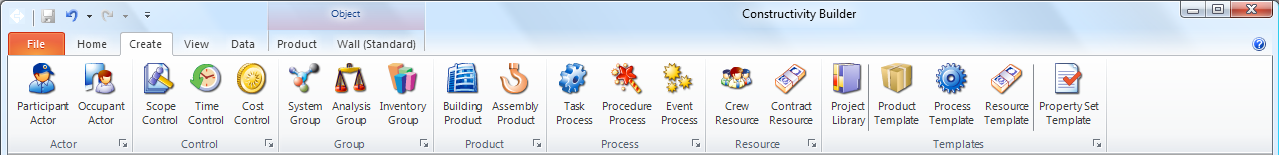
Each ribbon bar has a launcher button which displays the Workspace tab where corresponding objects are created.
The Actor ribbon bar is used to declare people and organizations.
| Command | Description |
 Project Actor |
Creates a person or organization involved in the project.
Project actors may be composed by the following:
|
 Occupant Actor |
Creates a person or organization to occupy a building or space.
Project actors may be composed by the following:
|
The Control ribbon bar is used to declare requirements and track scope, time, cost, or quality.
| Command | Description |
 Scope Control |
Creates a project order to encompase a scope of work. Project orders may be composed by the following:
|
 Time Control |
Creates a work plan for tracking activities over time. Work plans may be composed by the following:
|
 Cost Control |
Creates a cost item, consisting of a breakdown of costs for a project. Costs items may be composed by the following:
|
 Quality Control |
Creates performance history for predicting or recording actual conditions over time. Performance history may be composed by the following:
|
The Group ribbon bar is used to declare systems, analysis models, and other groups.
| Command | Description |
 System Group |
Creates a system group for building systems, distribution systems, and zones. System groups may be composed by the following:
|
 Analysis Group |
Creates a structural analysis model. Analysis models may be composed by the following:
|
 Inventory Group |
Creates an inventory group. Inventories may be composed by the following:
|
The Product ribbon bar is used to declare building structures.
| Command | Description |
 Site Product |
Creates a building site reflecting a geographic location and boundaries. Sites may be composed by the following:
|
 Building Product |
Creates a standalone building without any site defined. Buildings may be composed by the following:
|
The Process ribbon bar is used to declare tasks, procedures, and events in time.
| Command | Description |
 Event Process |
Creates an event which defines a condition for triggering processes. Events may be composed by the following:
|
 Procedure Process |
Creates a procedure which defines an arbitrary process. Procedures may be composed by the following:
|
 Task Process |
Creates a task which defines a scheduled process. Tasks may be composed by the following:
|
The Resource ribbon bar is used to declare internal and external resources.
| Command | Description |
 Crew Resource |
Creates a crew resource for materials, labor, and equipment under internal control. Crew resources may be composed by the following:
|
 Contract Resource |
Creates a subcontract resource for products or services under external control. Subcontract resources may be composed by the following:
|
The Template ribbon bar is used to declare object type definitions.
| Command | Description |
 Project Library |
Attaches a project library containing referenced templates for products, processes, resources, or properties. A wizard is launched for selecting project libraries. |
 Product Template |
Creates a product type such as indicating a product model. A wizard is launched for specifying the particular type and source of data (see below). |
 Process Template |
Creates a process type such as indicating shared construction procedures. A wizard is launched for specifying the particular type and source of data (see below). |
 Resource Template |
Creates a resource type such as indicating shared resource productivity. A wizard is launched for specifying the particular type and source of data (see below). |
 Property Template |
Creates a property set template for indicating details on objects of particular types. A wizard is launched for specifying the particular type and applicable entity. |
Upon clicking a button to create an object, a wizard is displayed consisting of multiple steps.
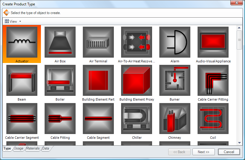
The wizard contains multiple tabs for each step, where the Next button advances to the next step and the Back button goes to the previous step. A choice made in an earlier step often determines options available in later steps. In the table below, an asterisk indicates dependent steps.
| Step | Description |
| Type | Indicate the object type to create. |
| Usage | Indicate the usage type (or subtype) to create. |
| Materials* | Indicate material constituents, layers, or profiles. [Product Templates] |
| Data | Indicate an optional external source of data, or finish the wizard. |
| Classification* | Indicate a classification to import. [Data indicates classification type] |
| Document* | Indicate a document to import. [Data indicates document type] |
| Library* | Indicate a library to import. [Data indicates library type] |
| Aspects* | Indicate rows and columns to import. [Data indicates generic format] |
View Ribbon
The View ribbon bar switches between viewing modes for the active workspace. The view can also be adjusted using the small buttons on the lower right of the status bar.
| Command | Description |
Icon View |
View objects as icons or thumbnail previews. This view is useful for browsing product types according to graphical image or photo. |
 List View |
View objects in tabular form. This view is useful for browsing objects by detailed summaries. |
 Item View |
View items in graphical detail.
|
 Full Screen |
View in full-screen mode, suitable for presentations, kiosks, or control panels. In full-screen mode, the mouse, keyboard, and remote controls are used for navigation:
|
The Camera ribbon bar adjusts 3D angle and projection.
| Command | Description |
 Camera Elevation |
Switches to camera presets including side elevations, corner angles, and overhead plan view.
|
 Camera Projection |
Switches between perspective and isometric projections.
|
 Camera Operation |
Switches between camera navigation modes.
|
The Render ribbon bar changes the current rendering mode.
| Command | Description |
 Draft Render |
Renders items using simplified representations.
|
 Model Render |
Renders items using detailed representations.
|
The Time ribbon bar allows the project to be viewed at a particular point in time.
| Command | Description |
 Time |
View items throughout the entire lifecycle, start, end, or somewhere in between.
|
 Animate |
Show construction sequences progressing through time forwards or backwards.
|
The Filter ribbon bar allows items to be shown or hidden according to type.
| Command | Description |
 Filter Selection |
Includes a filter for the type of the current selection, and sets the filter to off to hide all objects of such type. Filters are useful for accessing objects that are obscured, such as by hiding roofs or coverings. Configured filters vary according to the type of the container object. For example, a Site has filters for Annotations and Grids by default, while a Building has a filter for Roof. The gallery of filters indicates which types are shown or hidden according to the pressed state of the button. Inherited types may be used to show or hide a broad class of objects, where a visible filter takes precedence. For example, all distribution elements may be hidden except for air terminals by having "Distribution Element" turned off and "Air Terminal" turned on. |
| Filter Launcher | Launches the Filter Dialog for adding or removing filters. |
Data Ribbon
The Context ribbon bar supports adjusting project-wide settings including units and coordinate system.
| Command | Description |
| Unit Measures | Define default engineering units and currency. |
| Coordinate Systems | Define coordinate systems and precision. |
The Attributes ribbon bar supports defining property sets or quantities for objects.
| Command | Description |
| Include Properties | Choose property sets to define on the selected object. |
| Include Quantities | Choose quantities to define on the selected object. |
The Access ribbon bar allows reserving the current object for exclusive editing if connected to a model server.
| Command | Description |
| Read-Write | Object can be viewed and edited. |
| Read-Only | Object is can be viewed but not edited. |
| No Access | Object cannot be viewed or edited. |
| Lock Object | Lock object for exclusive editing. |
The Association ribbon bar allows associating the current object to external classifications, documents, or libraries.
| Command | Description |
| Classification | Associate classifications such as MasterFormat, vendor product classification, work breakdown structure, or building automation system address scheme. |
| Document | Associate documents such as text files, images, and various vendor formats. |
| Library | Associate libraries such as databases and IFC project libraries. |
Style Ribbon
The Style Ribbon is displayed if a geometric shape is selected. It contains commands for editing presentation styles in both Draft Rendering and Model Rendering modes.

The Curve ribbon bar is used to set colors and patterns for lines viewed for Draft Rendering.
| Command | Description |
| Curve Color | Sets the color of lines. |
| Dashes | Sets the dash pattern of lines. |
| Weight | Sets the thickness of lines. |
| (Dialog Launcher) | Launches the Curve Style Dialog for custom line settings. |
The Fill Area ribbon bar is used to set colors and patterns for fill areas viewed for Draft Rendering.
| Command | Description |
| Fill | Sets the color of fill regions. |
| Hatch | Sets the hatch pattern of fill regions. |
| (Dialog Launcher) | Launches the Fill Area Dialog for custom fill settings. |
The Text ribbon bar is used to set fonts for annotations viewed for Draft Rendering.
| Command | Description |
| Font Family | The upper left dropdown box selects the font family such as Arial or Courier. |
| Font Size | The upper right dropdown box selects the font point size. |
| Bold | Toggles the bold state of the font. |
| Italic | Toggles the italic state of the font. |
| Underline | Toggles the underline state of the font. |
| Text Foreground Color | Sets the foreground text color. |
| Text Background Color | Sets the background text color. |
| (Dialog Launcher) | Launches the Text Style Dialog for custom font settings. |
The Surface ribbon bar is used to set colors, textures, and reflectance for shapes viewed for Model Rendering.
| Command | Description |
| Surface | Sets a solid color for the surface appearance. |
| Effect | Sets a reflectance effect for the surface appearance. |
| Texture | Sets a texture for the surface appearance. |
| (Dialog Launcher) | Launches the Surface Style Dialog for custom surface settings. |
The Presentation Style ribbon bar contains a gallery of recently used styles for quickly applying appearance settings.
| Command | Description |
| Gallery | Contains buttons for recently used styles, where clicking a button applies the style to the current selection. |
| (Dialog Launcher) | Launches the Presentation Style Dialog for editing the current style as a whole. |
The Curve Style Dialog allows editing colors and patterns for lines.

Several predefined patterns are provided; custom patterns may be defined by specifying visible and invisible line segments.
The Fill Area Style Dialog allows editing colors and patterns for fill regions.

Several predeined patterns are provided; custom patterns may be defined by specifying hatch lines of various styles and angles.
The Text Style Dialog allows editing colors and fonts for text.

Font sizes and text dimensions are specified by physical length as viewed in the building model, which may be transformed according to representation contexts for annotations.
The Surface Style Dialog allows editing colors, textures, and reflectance for the surface of a material.

Diffuse textures and colors indicate the basic appearance; Specular indicates direct reflection of light; Reflection indicates scattered reflection of light; Opacity indicates transmission of light through substances. To set or clear a texture for a particular aspect, click on the corresponding square button to launch the Texture Dialog.
The Texture Dialog allows editing textures and mapping dimensions to the physical world.

Textures may be stored within the building model directly or external; an Image texture indicates external file; a Blob texture is compressed within the file; and a Pixel texture is expanded within the file. Image textures are recommended for best results, for optimal file loading and saving efficiency, and external images are automatically uploaded to a model server.
It is important to set the Physical Width and Physical Height of any texture such that it appears properly when scaled on a building. If such dimensions are not specified, then the dimensions default to 1 meter if using metric units or 4 feet if using imperial units.
Actor Workspace
The Actor Ribbon is displayed if a person or organization is selected and contains commands for editing the selection.
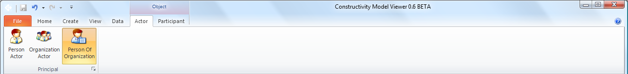
The Principal ribbon bar is used to set identification, roles, and address information.
| Command | Description |
| Person Actor | Indicates the actor is a person acting independently. |
| Organization Actor | Indicates the actor is an organization or department. |
| Person of Organization | Indicates the actor is a person acting on behalf of an organization. |
| (Dialog Launcher) | Launches the Actor Dialog to edit contact information. |
The Actor Dialog allows specifying identity, roles, and addresses.

Lists can be edited by using dropdown buttons to Add, Edit, or Delete information. Adding or editing addresses may launch the Postal Address Dialog or Telecom Address Dialog.
The Postal Address Dialog allows specifying physical addresses.

In certain regions, address information may be automatically populated by specifying the country and postal code.
The Telecom Address Dialog allows specifying electronic addresses.

The specified phone numbers or email addresses may be used to initiate communication from within the application.
Control Workspace
The Control Workspace supports viewing and editing of cost controls, time controls, scope controls, and quality controls. Cost controls include Cost Schedules with containing Cost Items. Time controls include Work Plans, Work Calendars, and Work Schedules. Scope controls include Project Orders, Permits, and Requests. Quality controls include Performance History.
The Approval ribbon bar is used for indicating approval or rejection of items.
| Command | Description |
| No Approval | Indicates no approval has been requested or acted upon. |
| Approval Requested | Indicates approval has been requested and outstanding. |
| Approval Pending | Indicates approval is on hold by at least one party. |
| Approval Denied | Indicates approval has been rejected by at least one party. |
| Approval Approved | Indicates approval has been accepted by all parties. |
The Constraint ribbon bar is used for applying constraints on the current selection.
| Command | Description |
| Minimum Value | Indicates the selected item is constrained by a minimum value. |
| Maximum Value | Indicates the selected item is constrained by a maximum value. |
Group Workspace
The Group Workspace supports editing of groups including Structural Analysis Models, Building Systems, Distribution Systems, Inventories, and Assets.
The Group ribbon bar is used for automatically generating members of the group.
| Command | Description |
| Populate System | Launches a wizard to create members for the system arranged according to parameters. |
| Design System | Launches a dialog to choose a building structure, and generates members to accomodate the structure. |
| Split System | Splits the current system into subsystems based on connectivity. |
The Analysis ribbon bar is used for evaluating the selected group or system.
| Command | Description |
| Run Analysis | Analyzes the selected system or group, clearing any existing results. |
| Clear Analysis | Clears analysis results. |

Structural Analysis Models support editing Curve Members, Surface Members, Connections, Loads, Load Cases, and Load Combinations. Analysis may be run at any time from the Group ribbon bar to evaluate Load Groups and generate resulting reactions.
Curve Members are inserted by selecting the Curve Member tool, clicking on (1a) the grid or (1b) an existing Point Connection, and then (2a) releasing the button in the same location to create a vertical member, (2b) dragging onto the grid to create a horizontal member, or (2c) dragging to an existing Point Connection to connect.
Surface Members are inserted by selecting the Surface Member tool, clicking on (1a) the grid or (1b) an existing Member Connection, and then (2a) dragging onto the grid to create a horizontal surface, or (2b) dragging to an existing Member connection to connect.
Point Connections are automatically created with Curve Members and Surface Members. Boundary conditions may be specified by selecting a connection and either clicking an icon from the Point Connection ribbon gallery or launching the Boundary Condition Dialog to edit details.
Load Cases and Load combinations may be created by selecting the corresponding tool and clicking anywhere in the view. Icons are displayed for load cases along the X grid axis, and for load combinations along the Y grid axis. Clicking an icon will display any loads and results within the load group. Double-clicking an icon will switch to the indicated load group in the 3D view for editing loads. Details of Load Cases and Load Combinations can be edited within the Property Grid.
With a Load Case displayed in 3D view, Point Loads, Curve Loads, and Surface Loads may be inserted.
Point Loads are inserted by selecting the Point Load tool, and clicking on a Point Connection, Curve Member, or Surface Member. By default, a point load will have a nominal force in the downwards direction (-Z) if placed on horizontal members, or a nominal force eastwards (+X) on vertical members.
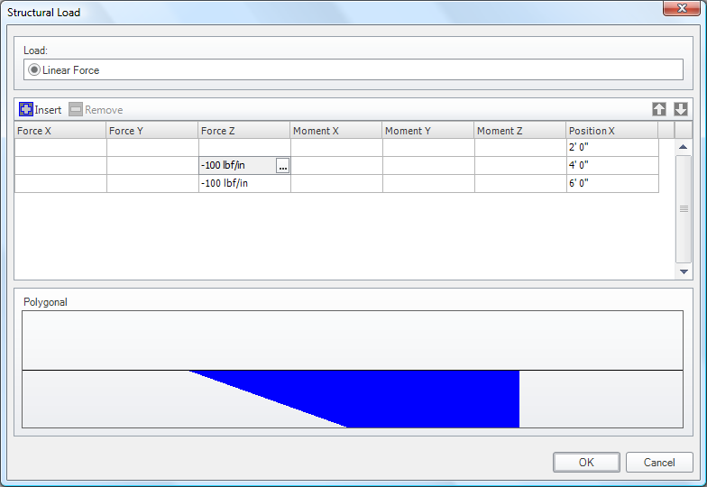
Curve Loads are inserted by selecting the Curve Load tool, clicking on a Curve Member and then (a) releasing the button in the same location to create a constant load filling the entire span, or (b) dragging along the member to create a linear load within the specified span.
Surface Loads are inserted by selecting the Surface Load tool, clicking on a Surface Member and then (a) releasing the button in the same location to create a constant load filling the entire area, or (b) dragging along the surface to create a rectangular load within the specified area.
Load forces and moments may be specified by selecting a load and clicking an icon from the Curve Load or Surface Load ribbon (as applicable) to indicate the load pattern, and launching the Load Dialog to edit details.
Product Workspace

The Material ribbon bar is used to set material application.
| Command | Description |
| Material Layer Set | Material Layers are used to fill the FootPrint Representation of the product. |
| Material Profile Set | Material Profiles are used to follow the Axis Representation of the product. |
| Material Constituent Set | Material Constituents are used to apply to Shape Aspects of the product. |
| Material Solid | A single solid material fills the geometry of the object. |
| (Dialog Launcher) | Launches the Material Dialog to edit material components, properties, and styles. |
The Placement ribbon bar is used to set the precise position and orientation of an object, as an alternative to using the graphical tools such as the Move Tool.
| Command | Description |
| Local Placement | Places the object locally relative to its container and indicates such state if the button is latched. |
| Grid Placement | Places the object relative to a grid within its container and indicates such state if the button is latched. |
| (Dialog Launcher) | Launches the Placement Dialog for precise editing of the position and orientation. |
The Representation ribbon bar is used to set details of geometric shapes, as an alternative to using the graphical tools.
| Command | Description |
| Annotation | Access annotation points, curves, and text literals. |
| Axis | Access axis curve for defining curved segments such as beams or pipes. |
| Footprint | Access footprint area for defining filled regions such as slabs or building footprints. |
| Profile | Access profile area for defining opening regions such as doors or windows. |
| Survey Points | Access survey points for defining site contours. |
| Lighting | Access light sources for defining light emission for lamps and light fixtures. |
| Clearance | Access clearance for defining unobstructed volumes such as needed for maintenance. |
| Body | Access 3D shape for defining shape geometry of items. |
| (Dialog Launcher) | Launches the Representation Dialog. |
The Material Dialog allows specifying materials, layers, profiles, or constituents.

Material components are shown in the grid, where specific material components and profiles can be edited by selecting a cell in the grid and clicking the "..." button to launch corresponding dialogs.
The Profile Dialog allows specifying 2D profile shapes to be used with material profiles or swept solid geometry.
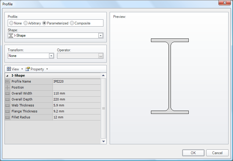
Profiles can be transformed from parameterized into arbitrary or into composite profile types. Profiles in arbitrary form may be edited by selecting the Outer Curve property and launching the Curve Dialog.
The Curve Dialog allows specifying polylines, arcs, and other curve types.
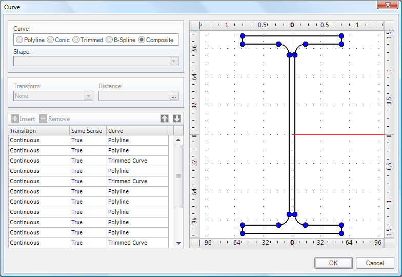
Curves can be transformed from arcs or composite curves into polylines. Such conversions may be lossy in that arcs are converted into line segments defaulting to 32 intervals within a circle.
The Representation Dialog allows inspecting details of geometry and transforming representation types.

Geometry can be transformed from swept solids or constructive solids into boundary representations or into mapped types. Such conversions may be lossy in that curved surfaces are converted into planar faces. Details of geometry may be edited by selecting properties and launching corresponding dialogs.
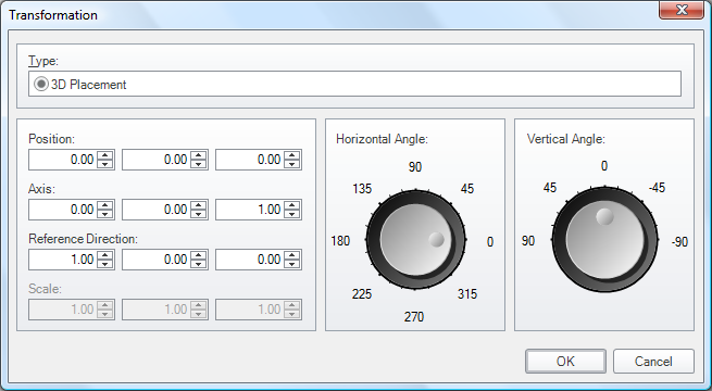
The Placement Dialog allows setting an object's position and orientation directly.
Process Workspace
The Process Ribbon is displayed if a process or process type is selected and contains commands for editing the selection.

| Command | Description |
| Estimated Duration | Indicates the task duration is a placeholder guess. |
| Measured Duration | Indicates the task duration is a confirmed value. |
| Simulated Duration | Indicates the task duration is calculated based on output quantity and resource productivity. |
| Recurring Task | Indicates task is recurring, where subtasks indicate individual recurrences. |
| (Dialog Launcher) | Launches the Task Time Dialog to edit detailed task time information and optional recurrence patterns. |
The Task Constraint ribbon bar is used to apply constraints to the task such as fixed duration and/or fixed dates.
| Command | Description |
| Fixed Work | Indicates the task has a fixed amount of work, which is typically the case for tasks resulting in building elements placed. |
| Fixed Usage | Indicates the task has fixed resource usage, which is typically the case for leased equipment and overhead. |
| Fixed Duration | Indicates the task has fixed duration, which is typically the case for lead times and meetings. |
| Fixed Dates | Indicates the task has fixed dates (also implying fixed duration), which may be the case for customer or regulatory mandates. |
| (Dialog Launcher) | Launches the Constraint Dialog for indicating custom constraints. |
The Task Time Dialog allows specifying durations, start, and end dates.
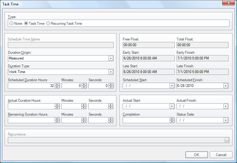
The Type indicates None if the task is not scheduled, Task Time if scheduled for a single period, or Recurring Task Time if scheduled for multiple periods. For recurring tasks, click the "..." button on the Recurrence field to launch the Task Recurrence Dialog.
The Task Recurrence Dialog allows specifying recurrence patterns for a task or calendar.

One or more time periods may be set to indicate the times of day when a task occurs. Note: calendars may have no times defined to indicate non-work days.
Resource Workspace
The Resource Workspace supports viewing and editing of labor, equipment, and materials.
The Resource Ribbon is displayed if a resource or resource type is selected and contains commands for editing the selection.
The Resource Work ribbon bar is used to set the total amount of the resource.
| Command | Description |
| Estimated Work | Indicates the resource work is a placeholder guess. |
| Measured Work | Indicates the resource work is a confirmed value. |
| Simulated Work | Indicates the resource work is calculated based on output quantity and resource productivity. |
| (Dialog Launcher) | Launches the Resource Work Dialog to edit detailed resource work information. |
The Resource Constraint ribbon bar is used to apply constraints to the task such as fixed duration and/or fixed dates.
| Command | Description |
| Fixed Work | Indicates the resource has a fixed amount of work, which is typically the case for tasks resulting in building elements placed. |
| Fixed Usage | Indicates the resource has fixed usage, which is typically the case for leased equipment and overhead. |
| Fixed Duration | Indicates the resource has fixed duration, which is typically the case for overhead. |
| (Dialog Launcher) | Launches the Constraint Dialog for indicating custom constraints. |
The Resource Time Dialog allows specifying work, usage, and availability.

If the Data Origin is set to Simulated, then values are automatically calculated.
The Resource Cost Dialog allows specifying resource cost values.

If the Data Origin is set to Simulated, then values are automatically calculated.
Spatial Elements
Spatial elements include sites, buildings, storeys, spaces (rooms), and annotations.
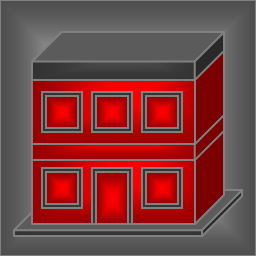 Building Building |
A Building may be inserted within a Site or may be created as a top-level object from Create - Spatial Element. By default, a building is created with a rectangular footprint, a single storey containing a single space, concrete slab, exterior walls, and a hipped roof. To edit the footprint, switch to Design Mode; use the Move tool to move vertices or split segments. Click on a point and drag to open space to move the point, or drag onto another point to combine segments in between. Click on a segment and drag to split the segment into two, and drag the resulting point to move its position. Upon modifying the footprint, the slab, exterior walls, and roof will be regenerated. To edit the interior of a building drill into a storey using the container tree bar above the 3D view. A building may contain Building Storeys which may be added using the Insert tool or removed by using the Select tool to select and delete a storey. |
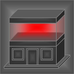 Building Storey Building Storey |
A Building Storey may be inserted within a Building using the Insert tool and clicking on an existing storey where it is to be inserted above. Upon inserting a storey, existing storeys will be shifted upwards. A storey may be deleted by navigating to the enclosing Building (using the container tree bar above the 3D view), selecting and clicking Delete. Deleting a storey will shift any storeys above downwards. Storeys are the primary container of building elements where walls, doors, windows, fixtures, etc. may be inserted. |
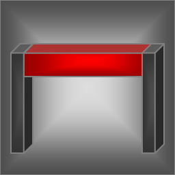
 Site Site |
A Site is a top-level object that may be created from Create - Spatial Element.
A site is defined by a boundary footprint and elevation contours. By default, a site is created with a rectangular footprint and flat elevation. To edit the contour, switch to Design Mode; use the Select tool to pick existing vertices or curves to adjust using the property grid, use the Insert tool to add elevation points; use the Move tool to move vertices, move elevation points, or split segments. A site may contain Buildings or any element directly. |
 Space Space |
A space may be inserted within a Building Storey using the Insert tool, or may be inserted automatically by connecting walls to form an enclosed region.
A space is defined by a boundary footprint which may be edited similar to building footprints. A space may have Coverings for floors, walls, or ceilings using the Insert Tool set to Cover Space / Covering / Flooring (or other subtype). A space may directly contain Furniture; all other elements are placed relative to the containing Building Storey. |
Building Elements
Building elements include walls, slabs, doors, windows, beams, columns, stairs, and more.
 Beam Beam |
A beam may be inserted within a spatial structure (usually a Building Storey) or created automatically such as a lintel over a window opening. To insert a beam, in Object Mode choose the Insert Tool set to Contain Element / Beam. Upon placing, click on the position of one end (which may be on an existing beam or column for which to connect), and drag to either to another beam or column to connect or over the base slab for which to project a cantilever beam, and release the mouse button. A beam may have connections to other beams or columns. A beam may have Structural Curve Members assigned for structural analysis idealization. |
 Column Column |
A column may be inserted within a spatial structure (usually a Building Storey). To insert a column, in Object Mode choose the Insert Tool set to Contain Element / Column. Upon placing, move the mouse over a Slab or Plate and click to insert at the position of the mouse. By default, columns are created vertically with height extending to the building storey or roof above. A column may have connections to beams or other columns. A column may have Structural Curve Members assigned for structural analysis idealization. |
 Covering Covering |
A covering may be inserted within a Space or directly on a building element. To insert a covering, in Object Mode choose the Insert Tool set to Cover Space / Covering / Flooring (or other subtype). Upon placing, move the mouse over a Space and click to insert. A covering will be created at the floor, bounding walls, or ceiling of the space according to the type of covering. If any covered walls or slabs have openings, then corresponding openings are also made in the covering automatically. |
 Door Door |
A door may be inserted within a Wall. To insert a door, in Object Mode choose the Insert Tool set to Fill Element / Door / Single Swing Left (or other subtype). Upon placing, move the mouse to a position along a Wall and click to insert. An opening will be created within the wall for which the door fills. |
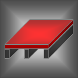 Slab Slab |
A slab may be inserted within a spatial structure (usually a Building Storey), or may be created automatically as part of a building storey, roof, stair, or ramp. To insert a slab, in Object Mode choose the Insert Tool set to Contain Element / Slab. Upon placing, click on the position of one corner, drag to the other corner, and release the mouse button. By default, a slab is created with a rectangular footprint. To edit the footprint, switch to Design Mode; use the Move tool to move vertices or split segments. Click on a point and drag to open space to move the point, or drag onto another point to combine segments in between. Click on a segment and drag to split the segment into two, and drag the resulting point to move its position. Upon modifying the footprint, any conflicting openings will be removed. A slab may contain Openings such as for staircases. A slab may have a Structural Surface Member assigned for structural analysis idealization. |
 Wall Wall |
A wall may be inserted within a spatial structure (usually a Building Storey), or exterior walls may be created automatically as part of a building storey. To insert a wall, in Object Mode choose the Insert Tool set to Contain Element / Wall. Upon placing, click on the position of one end (which may be on a slab or adjacent to an existing wall for which to connect), drag to the other end (which also may connect to an existing wall), and release the mouse button. If connections were made to other walls, then a Space will automatically be generated for any newly enclosed region. A wall may contain Openings optionally filled by elements such as doors, windows, junction boxes, light fixtures, and air terminals. A slab may have a Structural Surface Member assigned for structural analysis idealization. |
 Window Window |
A window may be inserted within a Wall. To insert a window, in Object Mode choose the Insert Tool set to Fill Element / Window. Upon placing, move the mouse to a position along a Wall and click to insert. By default, a window is created with a rectangular profile. To edit the profile, switch to Design Mode; use the Move tool to move vertices or split segments. Click on a point and drag to open space to move the point, or drag onto another point to combine segments in between. Click on a segment and drag to split the segment into two, and drag the resulting point to move its position. |
Structural Elements
Structural elements include footings, piles, and reinforcing.
 Footing Footing |
A footing may be inserted within a spatial structure (usually a Building). To insert a footing, in Object Mode choose the Insert Tool set to Contain Element / Footing. Upon placing a footing, click on the position of one end (which may be on an existing footing or pile for which to connect), and drag to either to another footing or pile to connect or over the site to position the other end, and release the mouse button. A footing may have connections to other footings, slabs, or walls. A footing may have Structural Curve Members assigned for structural analysis idealization. |
 Pile Pile |
A pile may be inserted within a spatial structure (usually a Building). To insert a pile, in Object Mode choose the Insert Tool set to Contain Element / Footing. Upon placing a pile, move the mouse over a Site and click to insert at the position of the mouse. By default, piles are created vertically extending below to a nominal depth. A pile may have connections to footings or columns. A pile may have Structural Curve Members assigned for structural analysis idealization. |
Mechanical Elements
Mechanical elements include equipment for heating, ventilation, and air conditioning (HVAC).
 Air Terminal Air Terminal |
An air terminal may be inserted within a Covering, such as a ceiling, flooring, or wall covering. To insert an air terminal, in Object Mode choose the Insert Tool set to Fill Element / Air Terminal. Upon placing, move the mouse over a Covering and click to place at the indicated position. An air terminal may have a port connection for air conditioning leading from a duct segment. Tip: to more easily access spaces or insides of walls, coverings may be shown or hidden according the filter from the View ribbon. |
 Boiler Boiler |
A boiler may be inserted on top of a Slab. To insert a boiler, in Object Mode choose the Insert Tool set to Contain Element / Boiler. Upon placing, move the mouse over a Slab and click to place at the indicated position. A water boiler has port connections for three pipes (domestic cold water in, domestic hot water out, gas in) and one duct (exhaust out). A steam boiler has port connections for three pipes (heating in, heating out, gas in) and one duct (exhaust out). |
 Chiller Chiller |
A chiller may be inserted on top of a Slab. To insert a chiller, in Object Mode choose the Insert Tool set to Contain Element / Chiller. Upon placing, move the mouse over a Slab and click to place at the indicated position. A chiller has aggregated Compressor, Condenser, and Evaporator elements forming a refrigeration loop. A chiller has port connections for pipes leading to cooling towers and unitary equipment such as air handlers. |
 Coil Coil |
A coil is aggregated within Unitary Equipment and is not normally created directly. A coil has two port connections for ducts and two port connections for pipes leading to a boiler or chiller. |
 Compressor Compressor |
A compressor may be inserted on top of a Slab or aggregated within a Chiller. To insert a compressor, in Object Mode choose the Insert Tool set to Contain Element / Compressor. Upon placing, move the mouse over a Slab and click to place at the indicated position. A compressor has two port connections for pipes. |
 Condenser Condenser |
A condenser may be inserted on top of a Slab or aggregated within a Chiller. To insert a condenser, in Object Mode choose the Insert Tool set to Contain Element / Condenser. Upon placing, move the mouse over a Slab and click to place at the indicated position. A condenser has port connections for pipes leading to compressors, evaporators, and cooling towers. |
 Cooling Tower Cooling Tower |
A cooling tower may be inserted on top of a Slab. To insert a cooling tower, in Object Mode choose the Insert Tool set to Contain Element / Cooling Tower. Upon placing, move the mouse over a Slab and click to place at the indicated position. A cooling tower has two port connections for pipes leading to condenser water. |
 Damper Damper |
A damper is aggregated within Unitary Equipment and is not normally created directly. A damper has two port connections for ducts, and may be connected to an actuator. |
 Duct Fitting Duct Fitting |
A duct fitting may be connected to duct-based ports of HVAC elements such as duct segments, air terminals, and air handlers (unitary equipment). To insert a duct fitting, in Object Mode choose the Insert Tool set to Connect Ports / Duct Fitting. Upon placing, move the mouse over a compatible port of an element, click to place at the indicated position, and drag to orient the fitting in a particular direction. A duct fitting has two or more port connections leading to other duct fittings, duct segments, or HVAC equipment. Change the Usage Type to indicate bends, junctions, transitions, or other forms. |
 Duct Segment Duct Segment |
A duct segment may be connected to duct-based ports of HVAC elements such as duct fittings, air terminals, and air handlers (unitary equipment). To insert a duct segment, in Object Mode choose the Insert Tool set to Connect Ports / Duct Segment. Upon placing, move the mouse over a compatible port of an element, click to place at the indicated position, and drag to align the segment along a particular path or connect to a port of another element. A duct segment has two port connections leading to other duct segments, duct fittings, or HVAC equipment. |
 Evaporator Evaporator |
An evaporator may be inserted within a spatial structure such as a Building Storey or aggregated within a Chiller. To insert an evaporator, in Object Mode choose the Insert Tool set to Contain Element / Evaporator. Upon placing, move the mouse over a Slab and click to place at the indicated position. An evaporator may have port connections leading to compressors, condensers, and coils. |
 Fan Fan |
A fan is aggregated within Unitary Equipment and is not normally created directly. A fan has two port connections for ducts and one port connection for electrical power. |
 Filter Filter |
A filter is aggregated within Unitary Equipment and is not normally created directly. A filter has two port connections for ducts. |
 Flow Meter Flow Meter |
A flow meter may be connected to pipe-based ports of HVAC and plumbing elements such as pipe fittings, pipe segments, and equipment. To insert a flow meter, in Object Mode choose the Insert Tool set to Connect Ports / Flow Meter. Upon placing, move the mouse over a compatible port of an element, click to place at the indicated position. A flow meter has two port connections leading to other pipe segments, pipe fittings, or equipment. |
 Pipe Fitting Pipe Fitting |
A pipe fitting may be connected to pipe-based ports of HVAC and plumbing elements such as pipe segments, sanitary terminals, coils, and chillers. To insert a pipe fitting, in Object Mode choose the Insert Tool set to Connect Ports / Pipe Fitting. Upon placing, move the mouse over a compatible port of an element, click to place at the indicated position, and drag to orient the fitting in a particular direction. A pipe fitting has two or more port connections leading to other pipe fittings, pipe segments, or equipment. Change the Usage Type to indicate bends, junctions, transitions, or other forms. |
 Pipe Segment Pipe Segment |
A pipe segment may be connected to pipe-based ports of HVAC and plumbing elements such as pipe fittings, sanitary terminals, coils, and chillers. To insert a pipe segment, in Object Mode choose the Insert Tool set to Connect Ports / Pipe Segment. Upon placing, move the mouse over a compatible port of an element, click to place at the indicated position, and drag to align the segment along a particular path or connect to a port of another element. A pipe segment has two port connections leading to other pipe segments, pipe fittings, or equipment. |
 Tank Tank |
A tank may be inserted on top of a Slab. To insert a tank, in Object Mode choose the Insert Tool set to Contain Element / Tank. Upon placing, move the mouse over a Slab and click to place at the indicated position. A tank has port connections for two pipes (in and out). |
 Unitary Equipment Unitary Equipment |
Unitary equipment (such as an air handler) may be inserted within a spatial structure such as a Building Storey. To insert unitary equipment, in Object Mode choose the Insert Tool set to Contain Element / Unitary Equipment. Upon placing, move the mouse over a Slab and click to place at the indicated position. A chiller has aggregated Damper, Filter, Cooling Coil, Heating Coil, and Fan elements. Unitary equipment has two port connections for ducts leading to air terminals and up to four port connections for pipes leading to boilers or chillers. |
 Valve Valve |
A valve may be connected to pipe-based ports of HVAC and plumbing elements such as pipe fittings, pipe segments, sanitary terminals, coils, and chillers. To insert a valve, in Object Mode choose the Insert Tool set to Connect Ports / Valve. Upon placing, move the mouse over a compatible port of an element, click to place at the indicated position. A valve has two port connections leading to other pipe segments, pipe fittings, or equipment. |
Electrical Elements
Electrical elements include light fixtures, outlets, switches, appliances, and more.
 Audio/Video Appliance Audio/Video Appliance |
An audio/video appliance may be inserted within a wall. To insert an audio/video appliance, in Object Mode choose the Insert Tool set to Fill Element / Audio-Video Appliance. Upon placing, move the mouse over a Wall and click to place at the indicated position. An audio-video appliance may have port connections to power and other audio-video appliances. |
 Cable Carrier Fitting Cable Carrier Fitting |
A cable carrier fitting may be connected to cable-based ports of electrical fittings such as distribution boards and junction boxes. To insert a cable fitting, in Object Mode choose the Connect Tool set to Connect Ports / Cable Carrier Fitting. Upon placing, move the mouse over a compatible port of an element, click to place at the indicated position, and drag to orient the fitting in a particular direction. A cable carrier fitting has two or more port connections leading to other cable carrier fittings or cable carrier segments. A cable carrier fitting also has additional port connections for cable segments entering or leaving the cable carrier. Change the Usage Type to indicate junctions, transitions, or other forms. |
 Cable Carrier Segment Cable Carrier Segment |
A cable carrier segment may be connected to cable-based ports of electrical fittings such as distribution boards and junction boxes. To insert a cable carrier segment, in Object Mode choose the Connect Tool set to Connect Ports / Cable Carrier Segment. Upon placing, move the mouse over a compatible port of an element, click to place at the indicated position, and drag to align the segment along a particular path or connect to a port of another element. A cable carrier segment has two port connections leading to other cable carrier segments or cable carrier fittings. |
 Cable Fitting Cable Fitting |
A cable fitting may be connected to cable-based ports of electrical elements such as junction boxes and light fixtures. To insert a cable fitting, in Object Mode choose the Connect Tool set to Connect Ports / Cable Fitting. Upon placing, move the mouse over a compatible port of an element, click to place at the indicated position, and drag to orient the fitting in a particular direction. A cable fitting has two or more port connections leading to other cable fittings, cable segments, or electrical equipment. Change the Usage Type to indicate junctions, transitions, or other forms. |
 Cable Segment Cable Segment |
A cable segment may be connected to cable-based ports of electrical elements such as junction boxes and light fixtures. To insert a cable segment, in Object Mode choose the Connect Tool set to Connect Ports / Cable Segment. Upon placing, move the mouse over a compatible port of an element, click to place at the indicated position, and drag to align the segment along a particular path or connect to a port of another element. A cable segment has two port connections leading to other cable segments, cable fittings, or electrical equipment. |
 Distribution Board Distribution Board |
A distribution board may be inserted within a wall. To insert a distribution board, in Object Mode choose the Insert Tool set to Fill Element / Distribution Board. Upon placing, move the mouse over a Wall and click to place at the indicated position. A distribution board may have port connections for one or more contained protective devices (circuit breakers), where each contained breaker leads to junction boxes or equipment. |
 Junction Box Junction Box |
A junction box may be inserted within a wall, or may be created automatically upon inserting a Switch or Outlet. To insert a junction box, in Object Mode choose the Insert Tool set to Fill Element / Junction Box. Upon placing, move the mouse over a Wall and click to place at the indicated position. A junction box may have port connections for one or more contained outlets or switches, and cables leading to other junction boxes and protective devices (circuit breakers) within distribution boards. |
 Lamp Lamp |
A lamp may be connected to lighting-based ports of light fixtures. Lamps are also created automatically with default light fixtures. To insert a lamp, in Object Mode choose the Connect Tool set to Connect Ports / Lamp. Upon placing, move the mouse over a compatible port of an element and click to place at the indicated position. A lamp has a single port connection to the hosting light fixture. |
 Light Fixture Light Fixture |
A light fixture may be inserted within a Wall or a Covering (particularly a ceiling covering). To insert a light fixture, in Object Mode choose the Insert Tool set to Fill Element / Light Fixture. Upon placing, move the mouse over a Wall or Covering and click to place at the indicated position. Note that ceiling coverings are not visible by default; to show ceiling coverings, toggle the filter from the View ribbon. A light fixture may have a port connection for power from a cable leading from a switch or distribution board. |
 Outlet Outlet |
An outlet may be contained within a Junction Box and inserted within a wall. To insert an outlet, in Object Mode choose the Insert Tool set to Fill Element / Outlet. Upon placing, move the mouse over a Wall or Junction Box and click to place at the indicated position. If placing within a junction box, the junction box will be expanded if necessary. If placing within a wall, a junction box will be automatically created to contain the outlet. An outlet may have port connections for its containing junction box and any connected appliances. |
 Switch Switch |
A switch may be contained within a Junction Box and inserted within a wall. To insert a switch, in Object Mode choose the Insert Tool set to Fill Element / Switch. Upon placing, move the mouse over a Wall or Junction Box and click to place at the indicated position. If placing within a junction box, the junction box will be expanded if necessary. If placing within a wall, a junction box will be automatically created to contain the switch. A switch may have port connections for its containing junction box and any connected light fixtures, fans, or other equipment. |
Plumbing Elements
Plumbing elements include sanitary terminals such as sinks, fire protection terminals, waste terminals, and stack terminals.
 Fire Suppression Terminal Fire Suppression Terminal |
A fire suppression terminal may be placed within a Covering, particularly a ceiling covering. To insert a fire suppression terminal, in Object Mode choose the Insert Tool set to Fill Element / Fire Suppression Terminal. Upon placing, move the mouse over a Covering and click to place at the indicated position. A fire suppression terminal has a single port connection for a pipe. |
 Sanitary Terminal Sanitary Terminal |
A sanitary terminal may be placed on a Slab, or may fill a countertop of a Furnishing Element. To insert a sanitary terminal, in Object Mode choose the Insert Tool set to Contain In Space / Sanitary Terminal. Upon placing, move the mouse over a Slab and click to place at the indicated position. A sanitary terminal has port connections for pipes, including domestic cold water, domestic hot water, and drainage. |